Quantum rod film

A quantum rod and prism technology, applied in nonlinear optics, instruments, optics, etc., can solve the problem that the brightening effect is not as good as expected, and achieve the effect of increasing the utilization rate

Active Publication Date: 2016-03-02
BENQ MATERIALS +1
View PDF4 Cites 17 Cited by
  • Summary
  • Abstract
  • Description
  • Claims
  • Application Information

AI Technical Summary

Problems solved by technology

[0008] In view of the problems of the above-mentioned conventional technical means, the purpose of the present invention is to provide a quantum rod film with the characteristics of novelty, ad...

Method used


Image

  • Quantum rod film
  • Quantum rod film
  • Quantum rod film

Examples


Embodiment Construction

[0024] In order to make the invention features, content and advantages of the present invention and the effects that can be achieved easier to understand, the present invention is hereby combined with the accompanying drawings, and is described in detail as follows in the form of embodiments, and the drawings used therein, its gist It is only for illustration and auxiliary description, not necessarily the true proportion and precise configuration of the present invention after implementation, so it should not be interpreted or limited to the scope of rights of the present invention in actual implementation based on the proportion and configuration relationship of the attached drawings. Explain first.

[0025] Hereinafter, embodiments of the quantum rod film according to the present invention will be described with reference to related drawings. For ease of understanding, the same components in the following embodiments will be described with the same symbols.
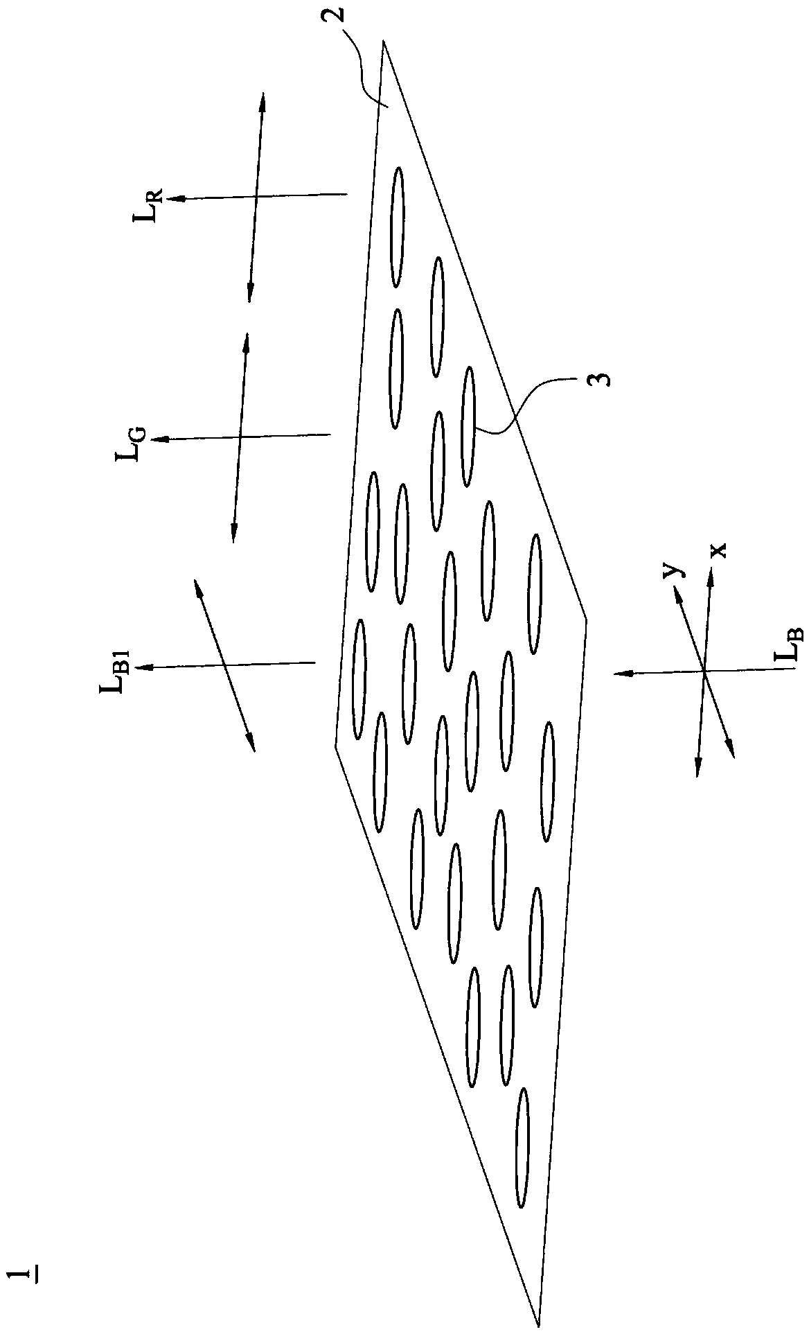
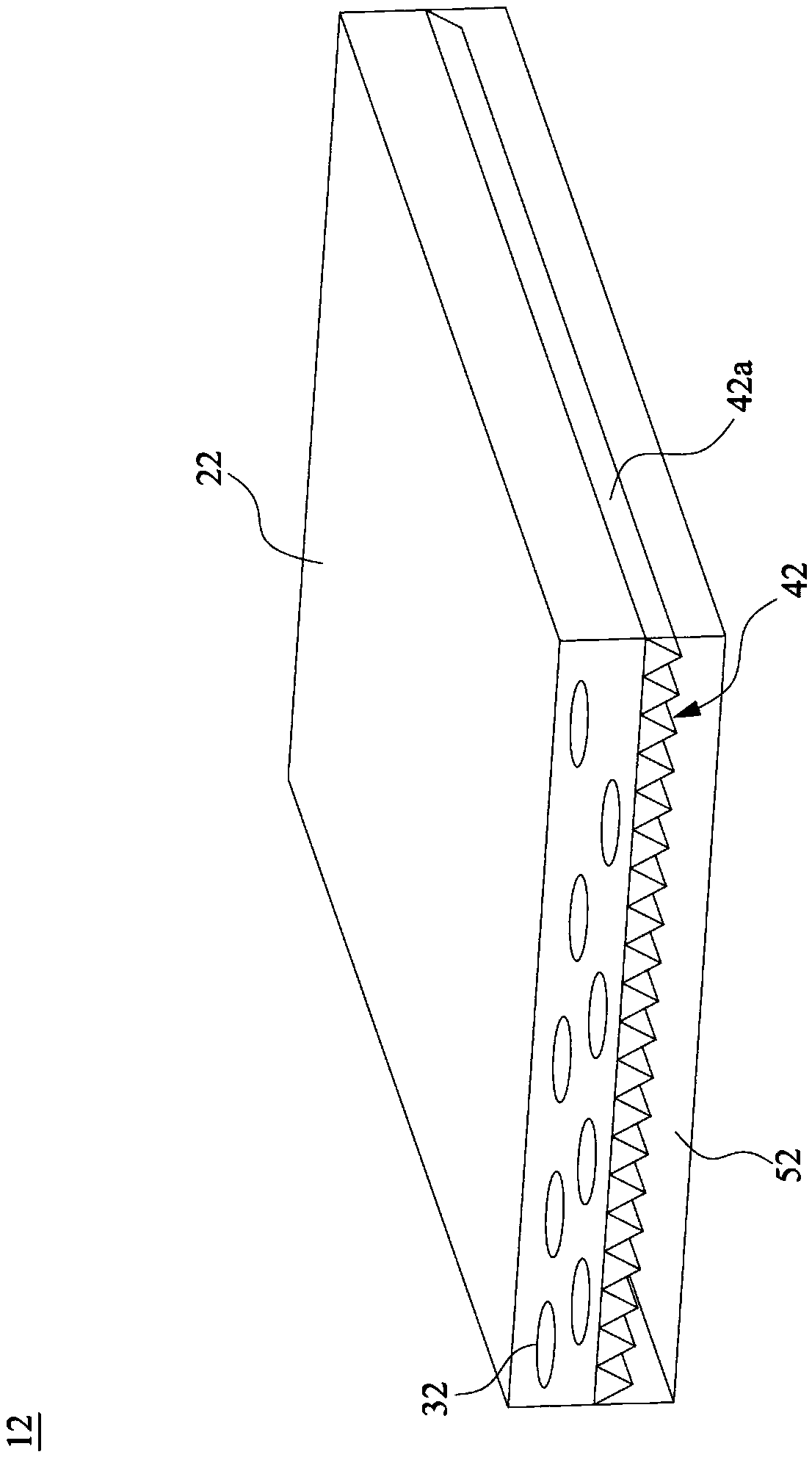
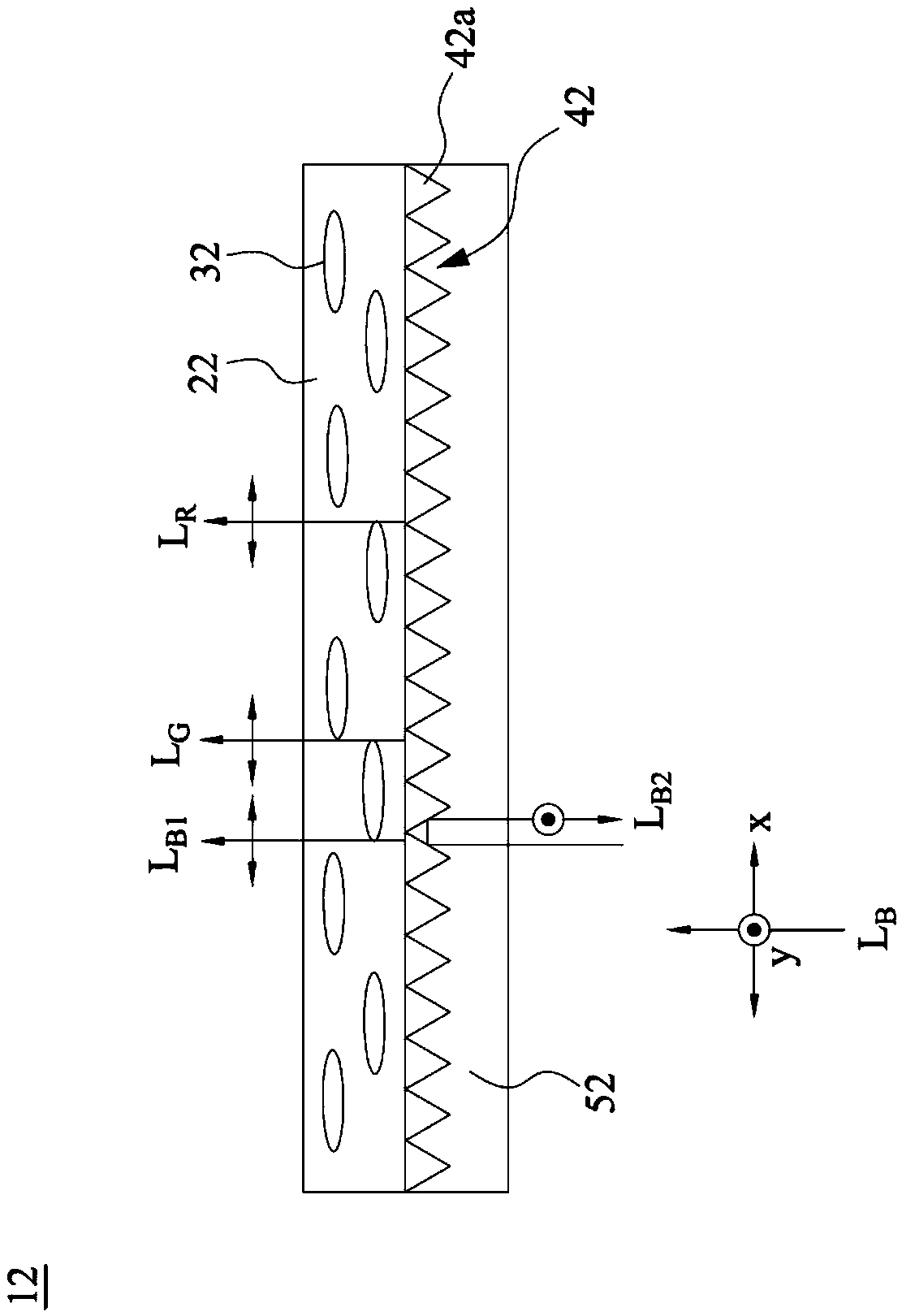
[0026] Please r...


PUM

PropertyMeasurementUnit
Top angleaaaaaaaaaa
Lengthaaaaaaaaaa

Abstract

The invention relates to a quantum rod film for a backlight module of a liquid crystal display. The quantum rod film comprises a quantum rod layer containing a plurality of quantum rods with long axles arrayed in one direction, a prism micro-structural layer having first refraction rate and a plurality of stripped prisms arrayed in a parallel way, and a double-refraction layer covering the prism micro-structural layer having abnormal light refraction rate or normal refraction rate, wherein the prism micro-structural layer is arranged on a light-incident side of the quantum rod layer; and due to the difference between the first refraction rate of the prism micro-structural layer and the abnormal light refraction rate or normal refraction rate of the double-refraction layer, light-incident light of the long axle direction of the plurality of quantum rods are selectively paralleled and light-incident lights perpendicular to the long axle direction of the plurality of quantum rods are reflected and recovered to strengthen back light source utilization rate.

Description

technical field [0001] The invention relates to a quantum rod film used in a backlight module of a liquid crystal display, so that the liquid crystal display has better color gamut and light source utilization rate. Background technique [0002] The polarizer used in conventional liquid crystal displays generally adopts the absorbing polarizer. When the non-polarized light emitted by the backlight passes through the polarizer, the component in the direction of the absorption axis of the polarizer will be absorbed and cannot pass through. Therefore, the transmittance of the polarizer to the backlight source can only reach below 50% in theory, and after the light passes through the electrode layer of the liquid crystal panel, the color filter, the liquid crystal layer and the glass substrate, the user can actually see the brightness of the display , then only 10% or less of what is emitted by the backlight is left, so the utilization rate of the backlight is quite low, resulti...

Claims


Application Information

Patent Timeline
IPC IPC(8): G02F1/13357G02F1/13363
CPCG02F1/1336G02F1/133606G02F1/13363G02F1/133607G02F1/133614
Inventor 吴建宏赵士维
Owner BENQ MATERIALS
Why Eureka
Try Eureka