Horology device for displaying time or time-derived information

A technology for displaying time and display devices, which is applied in the fields of date display devices, clock movements, and watches, and can solve the problems of complexity, huge production and implementation of display devices, etc.

Active Publication Date: 2016-03-02
MONTRES TUDOR
View PDF17 Cites 3 Cited by
  • Summary
  • Abstract
  • Description
  • Claims
  • Application Information

AI Technical Summary

Problems solved by technology

However, the structure involves a complex drive crown gear with auxiliary control pini

Method used


Image

  • Horology device for displaying time or time-derived information
  • Horology device for displaying time or time-derived information
  • Horology device for displaying time or time-derived information

Examples


Embodiment Construction

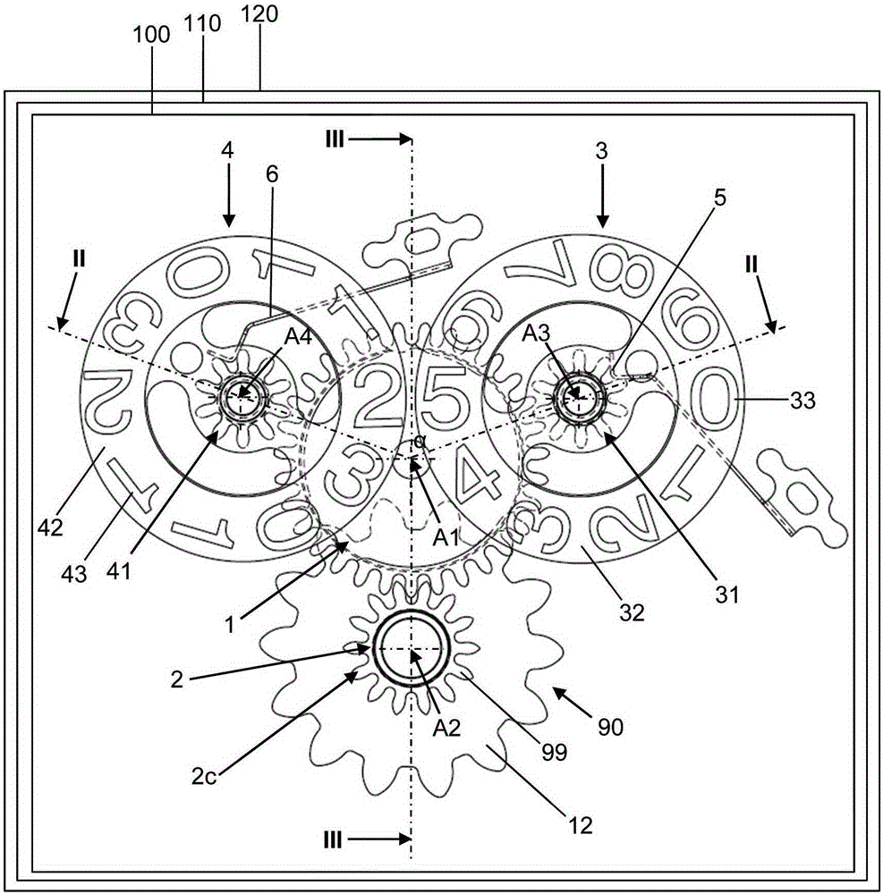
[0018] Preferably, the invention relates to a device for displaying time or time-derived information, in particular for displaying information of the "big date" type, in which the first Disc 1 and Disc 2 display information. A simplified use of a controlled movable member for controlling the tens and ones disc is proposed. The controlled movable members are arranged and configured in a way that rationalizes the construction of the device. This even further makes it possible to simplify and rationalize the construction of the timepiece movement intended to be contained. The controlled movable member also has the advantage of keeping the thickness needed to create the device as small as possible.

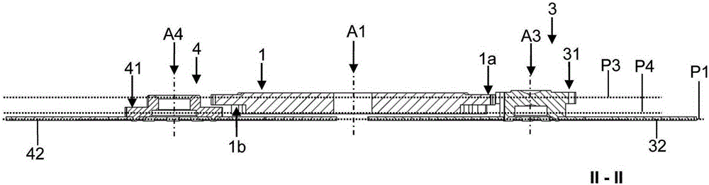
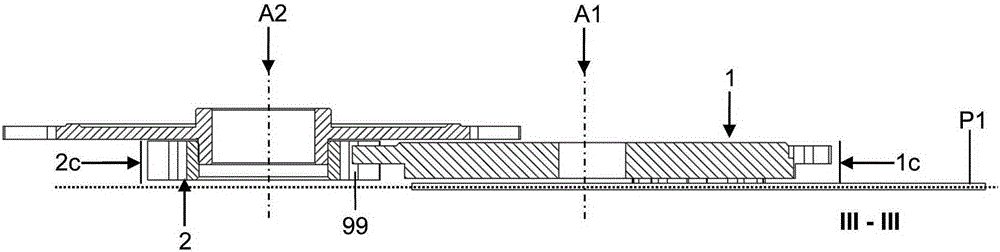
[0019] will refer to the attached Figures 1 to 8 A first embodiment of the timer 120 according to the present invention is described. For example, the timepiece is a watch, especially a wristwatch. The timepiece comprises a timepiece movement 110 according to the first embodiment...


PUM


Abstract

A device (100; 200) for displaying time information, including: a first mobile (3) including a first toothset (31) and a first disk (32) bearing numerals (33) which are intended to indicate the units of the time information, a second mobile (4) including a second toothset (41) and a second disk (42) bearing numerals (43) intended to indicate the tenths of the time information, and a mechanism (90) for driving the first and second mobiles, the mechanism: including a control mobile (1): including a third toothset (1a) arranged so as to collaborate by obstacle, with the first, toothset, a fourth toothset (1b) arranged so as to collaborate by obstacle, with the second, toothset, a drive wheel (2) including a fifth toothset (2c) designed to collaborate by obstacle, with the third and fourth toothsets.

Description

technical field [0001] The invention relates to a device for displaying time or time-derived information, in particular to a device for displaying a date. The invention also relates to a timepiece movement incorporating such a device. The invention finally relates to a timepiece, in particular a watch, comprising such a device or such a movement. In particular, the invention relates to a display device or mechanism of the "big date" type, meaning a date display using a first disc for the ones and a second disc for the tens. Background technique [0002] Many implementations or documents disclose time display controlled movable members divided into three layers. Traditionally, the first layer is formed by a first interface gear actuatable by a date display device driving movable member or a sun / moon driving movable member so as to allow the first interface gear to rotate by one each time the date changes. Angular pitch. The second and third gears for the second and third ...

Claims


Application Information

Patent Timeline
IPC IPC(8): G04B19/247G04B19/253
CPCG04B19/24G04B19/25G04B1/00G04B19/046
Inventor 威廉·卡雷诺雅辛·贝尔汉法尔
Owner MONTRES TUDOR
Why Eureka
Try Eureka