Shaft suspension locking device

A locking device and shaft locking technology, applied in the direction of the transmission device using synchronous propulsion components, etc., can solve the problems of the stern shaft being involved, poor operability, and affecting the ship's docking control, etc.

Active Publication Date: 2019-08-20
WUCHANG SHIPBUILDING IND
View PDF5 Cites 0 Cited by
  • Summary
  • Abstract
  • Description
  • Claims
  • Application Information

AI Technical Summary

Problems solved by technology

[0004] 1) After the stern shaft and stern tube are installed on the berth, the stern shaft has the risk of axial movement and slippage, thereby damaging the seal of the stern shaft and stern tube;
[0005] 2) After the ship's launching propeller touches the water and until the ship docks at the wharf, the propeller will rotate at high speed under the impetus of the water flow, which will affect the barge control of the ship's state, and the high-speed rotating propeller may be hit by the floating objects on the wharf. There is also the risk that the stern shaft will move back and forth under the impetus of the water flow and damage the seal of the stern tube; there is also the risk that construction personnel close to the stern shaft will be involved in the high-speed rotating stern shaft and be cut by sharp edges
[0006] 3) In the shafting alignment of the wharf, the propeller rotating at high speed driven by the complex water flow of the wharf may be damaged by floating objects on the water surface of the wharf; The risk of shaft, stern tube and stern shaft sealing; there is also the danger of construction personnel close to the stern shaft being involved in the high-speed rotating stern shaft and being cut by sharp edges; especially when aligning at the dock, the stern shaft is not only affected by bearings In addition to the support reaction force and the buoyancy of oil and water, there should be no additional external force, but the axial and circumferential displacement of the stern shaft must be limited.
[0008] In the past, the anti-rotation and anti-channeling of the stern shaft mostly used the traditional method of fixing the stern shaft with cables in the cabin or fixing the propeller with underwater cables, which had poor reliability and operability and considerable construction safety risks.

Method used


Image

  • Shaft suspension locking device
  • Shaft suspension locking device
  • Shaft suspension locking device

Examples


Embodiment Construction

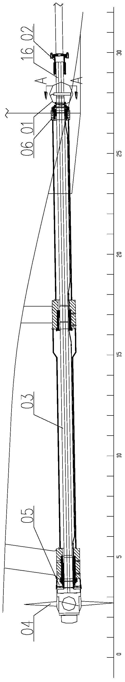
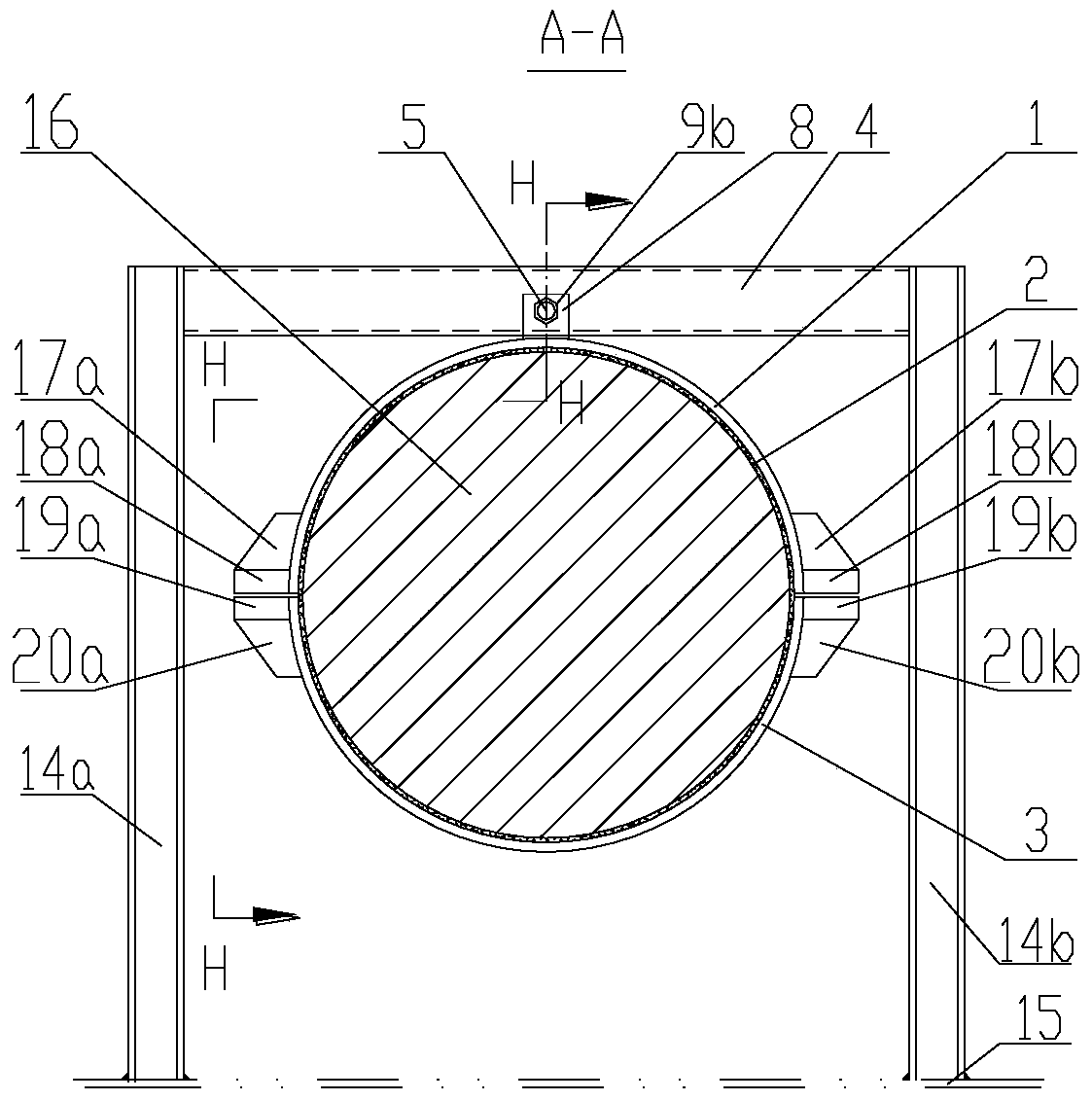
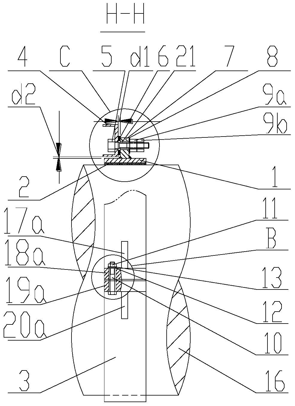
[0069] In order to solve the problems in the prior art, the present invention provides a shaft hanging locking device capable of preventing the shaft to be hung and locked from rotating or moving.

[0070] In order to further explain the technical means and effects of the present invention to achieve the intended purpose of the invention, the specific implementation, structure and characteristics of the shaft hanging locking device proposed according to the present invention will be described below in conjunction with the accompanying drawings and preferred embodiments. And its effect, detailed description is as follows. In the following description, different "one embodiment" or "embodiment" do not necessarily refer to the same embodiment. Furthermore, the particular features, structures, or characteristics of one or more embodiments may be combined in any suitable manner.

[0071] The term "and / or" in this article is just an association relationship describing associated ob...


PUM


Abstract

The invention discloses a shaft hoisting locking device and belongs to the technical field of engineering fixtures. The device comprises a fastener, a connecting piece and a fixed rack, wherein a circular holding space is formed in the center of the fastener, and a shaft can be locked in the holding space; and one end of the connecting piece is connected to the fastener, and the other end of the connecting piece is connected with the fixed rack. According to the invention, a shaft to be hoisted and locked is fixed to the fixed rack so as to avoid vertical displacement of the shaft to be hoisted and lock. Since the shaft to the hoisted and locked can penetrate through and be locked in the circular holding space in the center of the fastener, relative rotation generated between the shaft to be hoisted and locked and the fastener can be eliminated. When the device is used for hoisting and locking a ship propeller shaft, rotation or displacement of the ship propeller shaft can be eliminated.

Description

technical field [0001] The invention relates to the technical field of engineering fixtures, in particular to a shaft hanging locking device. Background technique [0002] After the ship stern shaft and propeller are positioned and installed on the berth, during the launching process of the ship, and before the centering connection and installation at the shafting wharf, in order to ensure the safety of the stern shaft, the construction personnel and the ship and the smooth progress of the shafting alignment, the stern shaft needs to be restricted. For the degrees of freedom in the axial, radial and circumferential directions, the stern shaft is to be provided with reliable positioning and fixing tooling to prevent the stern shaft from rotating and moving, and the tooling is not to be dismantled until the shafting is aligned and connected. [0003] If the stern shaft is not reliably positioned and fixed, there will be the following risks: [0004] 1) After the stern shaft a...

Claims


Application Information

Patent Timeline
Patent Type & Authority Patents(China)
IPC IPC(8): B63H23/35
Inventor 涂黎明胡昌浩秦启虎
Owner WUCHANG SHIPBUILDING IND
Why Eureka
Try Eureka