Z-shaped integrated radar transportation platform

A transportation platform and integrated technology, which is applied in the directions of transporting objects, transportation and packaging, and vehicles for freight transportation, etc., can solve the problems that the antenna base and the vehicle-carrying platform cannot meet the installation space requirements and bearing stiffness requirements of large-scale radar equipment, etc. Achieve the effect of eliminating left and right jitter, protecting stability and ensuring safety

Active Publication Date: 2021-02-02
CHINA ELECTRONIC TECH GRP CORP NO 38 RES INST
View PDF12 Cites 0 Cited by
  • Summary
  • Abstract
  • Description
  • Claims
  • Application Information

AI Technical Summary

Problems solved by technology

[0003] like figure 1 As shown, the reference size of the antenna array is 11m x 3m x 0.65m (length x width x height). The traditional antenna base and the vehicle platform are fixed by flanges and screws, which is a separate double U embedded type. Due to the high height of the antenna base, when rotating, the bottom of the antenna base must be higher than the upper surface of the gooseneck of the vehicle to realize the overall rotation of the antenna front, so the height of most multifunctional radars is greater than 4 meters. At the same time, when the antenna base is loaded with equipment In many cases, due to transportation restrictions, traditional antenna mounts and vehicle-mounted platforms cannot meet the installation space requirements and load-bearing rigidity requirements of large-scale radar equipment

Method used


Image

  • Z-shaped integrated radar transportation platform
  • Z-shaped integrated radar transportation platform
  • Z-shaped integrated radar transportation platform

Examples


Embodiment 1

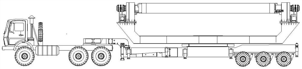
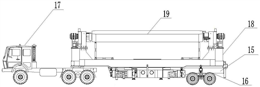
[0024] like figure 2 as shown, figure 2 It is a structural view of the Z-type integrated integrated radar transportation platform; the Z-shaped integrated integrated radar transportation platform of the present invention includes a vehicle 15, an axle 16, and an antenna seat 18 is connected to the vehicle 15, The antenna front 19 is arranged on the antenna base 18, the antenna base 18 is connected to the tractor 17, the axle 16 is connected to the side of the vehicle 15 away from the tractor 17, and the vehicle A bridge 16 is provided below the vehicle 15 . Through the structural setting of the Z-shaped integrated radar transport platform, the high maneuverability and erection requirements and the transport limit are achieved.

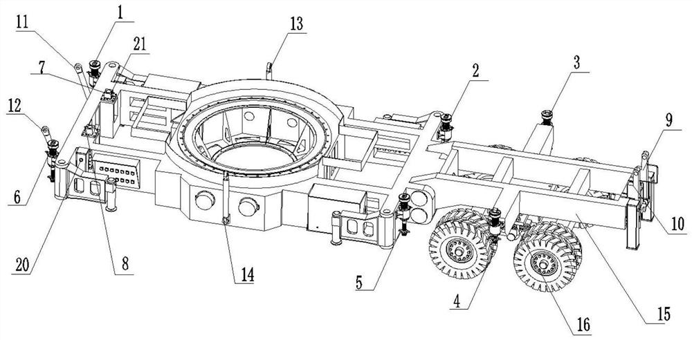
[0025] like image 3 as shown, image 3 It is a structural view of the vehicle; the vehicle 15 is provided with a first automatic positioning pin 7, a second automatic positioning pin 8, a first anti-swing positioning rectangular rod 9, and a sec...

Embodiment 2

[0037] like Figure 4 as shown, Figure 4 It is a structural view of the first twistlock; the first twistlock 1, the second twistlock 2, the third twistlock 3, the fourth twistlock 4, and the fifth twistlock 5 , The sixth twist lock 6 includes a twist lock bolt 31 , an upper screw body 32 , a nut sleeve 34 , a first nut 35 , a second nut 36 , a lead screw 39 , and a bearing 41 . The locking between the antenna base 18 and the vehicle 15 is realized by the twist lock.

[0038] The screw 39 is hollow, and the screw 39 is externally provided with threads; the nut sleeve 34 is sleeved on the screw 39, and the nut sleeve 34 and the screw 39 are threaded; generally Yes, the nut sleeve 34 is fixedly arranged, that is, the nut sleeve 34 is fixedly arranged on the vehicle through the housing 33 . The screw 39 is sleeved on the twist-lock bolt 31, and the two ends of the twist-lock bolt 31 are respectively provided with a fixing block and the second nut 36, and the twist-lock bolt 31...


PUM


Abstract

The invention discloses a Z-shaped integrated radar transportation platform which comprises a carrier vehicle and an axle, an antenna pedestal is connected to the carrier vehicle, an antenna array plane is arranged on the antenna pedestal, the antenna pedestal is connected with a tractor, the axle is connected to the side, away from the tractor, of the carrier vehicle, and the axle is arranged under the carrier vehicle; high-maneuverability erection requirements and transportation boundaries are met through self structure setting.

Description

technical field [0001] The invention relates to the technical field of vehicle radar, in particular to a Z-shaped integrated radar transportation platform. Background technique [0002] In order to realize the multi-directional scanning of the radar, the multi-function radar needs to be installed with an antenna base, and the multi-function radar can be transported by vehicle. [0003] like figure 1 As shown, the reference size of the antenna array is 11m x 3m x 0.65m (length x width x height). The traditional antenna base and the vehicle platform are fixed by flanges and screws, which is a separate double U embedded type. Due to the high height of the antenna base, when rotating, the bottom of the antenna base must be higher than the upper surface of the gooseneck of the vehicle to realize the overall rotation of the antenna front, so the height of most multifunctional radars is greater than 4 meters. At the same time, when the antenna base is loaded with equipment In man...

Claims


Application Information

Patent Timeline
Patent Type & Authority Applications(China)
IPC IPC(8): B60P7/135
CPCB60P7/135
Inventor 郭亚军何文杰吴影生房景仕张增太徐畅方莉
Owner CHINA ELECTRONIC TECH GRP CORP NO 38 RES INST
Why Eureka
Try Eureka