
Lift

A lifter and slider technology, applied in the lifter field, can solve the problems of inability to finely adjust the height of the worktable, poor reliability, and difficulty in meeting the actual needs of users.

Inactive Publication Date: 2016-03-09
WORLD TRANSMISSION TECH TIANJIN SHARE LTD
View PDF6 Cites 39 Cited by
  • Summary
  • Abstract
  • Description
  • Claims
  • Application Information

AI Technical Summary

Problems solved by technology

[0004] However, the folding and opening of the above-mentioned scissor mechanism is powered by a hydraulic cylinder, and it is impossible to finely adjust the height of the workbench, which is difficult to meet the actual needs of users.
[0005] In addition, the above-mentioned elevator is powered by a hydraulic cylinder, the system is highly complex, the reliability is poor, and the repair cost is high after damage

Method used


Image

  • Lift
  • Lift
  • Lift

Examples


Embodiment Construction

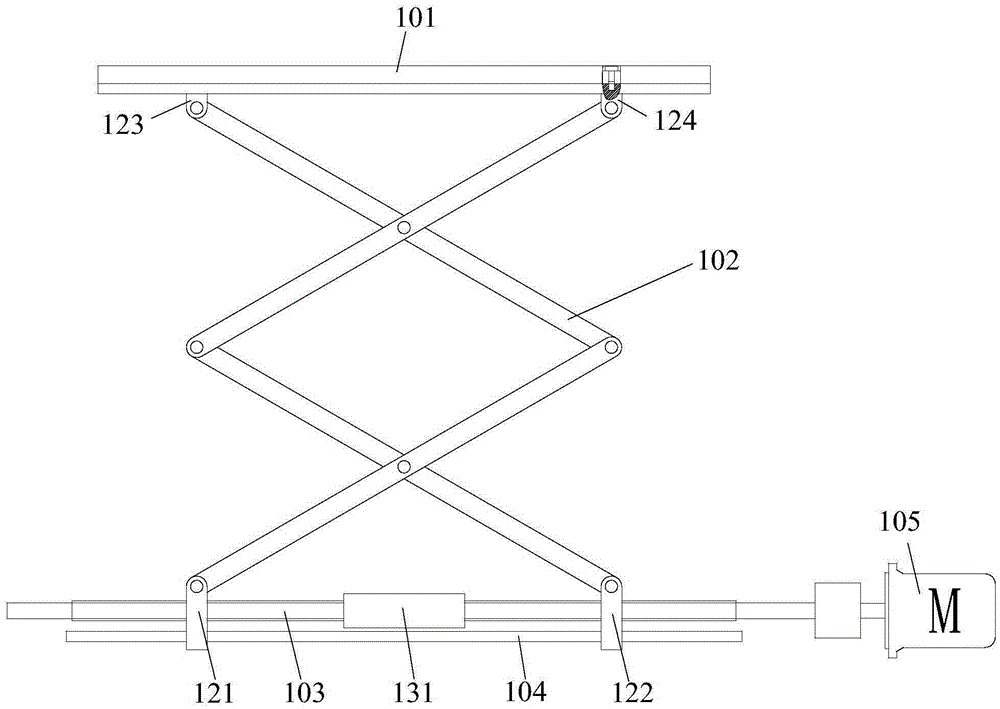
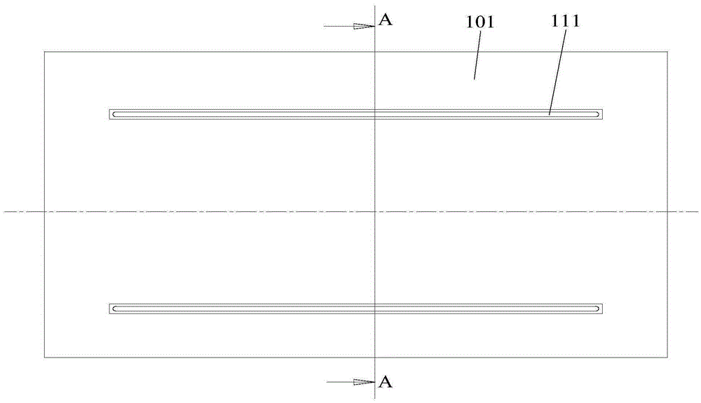
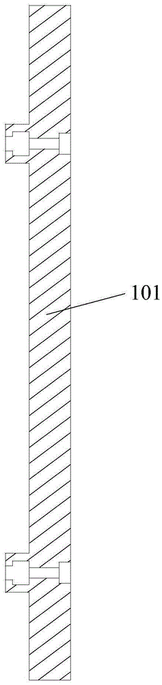
[0030] The embodiment of the present invention discloses a lift. The first slider and the second slider are respectively hinged to the two connectors of the first end of the scissor mechanism, and the first slider and the second slider are respectively threaded with the lead screw. Cooperate, the height of the platform set at the second end of the scissor mechanism can be adjusted by turning the lead screw during application. Obviously, the user can finely adjust the height of the above platform by controlling the number of turns of the lead screw, which is beneficial to meet the needs of users .

[0031] The following will clearly and completely describe the technical solutions in the embodiments of the present invention with reference to the accompanying drawings in the embodiments of the present invention. Obviously, the described embodiments are only some, not all, embodiments of the present invention. Based on the embodiments of the present invention, all other embodiment...


PUM


Abstract

The invention discloses a lift. The lift comprises a work platform, a shearing fork mechanism and a lead screw, wherein a first end of the shearing fork mechanism comprises a first connector and a second connector; the first connector is hinged to a first sliding block; the second connector is hinged to a second sliding block; a second end of the shearing fork mechanism is connected with the work platform; the first sliding block and the second sliding block are arranged on the lead screw in a sleeving mode and in threaded fit with the lead screw. The lead screw comprises a first threaded section and a second threaded section with opposite spiral directions, and the first sliding block and the second sliding block are matched with the first threaded section and the second threaded section respectively. When the lift is used, the first sliding block and the second sliding block are made to get close or far away by rotating the lead screw in different directions, and the work platform is lifted up or lowered. That is, a user can precisely adjust the height of the work platform by controlling the rotation circle number of the lead screw, and the requirement is met.

Description

technical field [0001] The invention relates to the technical field of machinery industry, more specifically, to a lift. Background technique [0002] As a common mechanical equipment, lifts are used in different industries, and scissor lifts are one of the more common ones. They are widely used in many fields due to their small space occupation (especially in the height direction). use. [0003] The above-mentioned scissor lift includes a scissor mechanism, the working end of the scissor mechanism is connected with a working platform, and the two connectors at the power end of the scissor mechanism are respectively connected to the piston rod and the housing of the hydraulic cylinder. When in use, the piston rod shrinks , the two connectors at the above-mentioned power end are close, the height of the scissors mechanism is increased, so that the working platform is raised, and the piston rod of the hydraulic cylinder is stretched out during storage, so that the two connect...

Claims


Application Information

Patent Timeline
IPC IPC(8): B66F7/06B66F7/28
CPCB66F7/0608B66F7/0666B66F7/28
Inventor 胡炜
Owner WORLD TRANSMISSION TECH TIANJIN SHARE LTD
Features
  • Generate Ideas
  • Intellectual Property
  • Life Sciences
  • Materials
  • Tech Scout
  • Unparalleled Data Quality
  • Higher Quality Content
  • 60% Fewer Hallucinations
Learn More