Stationary laser scanning equipment

A laser scanning, fixed technology, applied in the direction of electromagnetic radiation induction, etc., can solve the problems of affecting work, inconvenient maintenance, wrist oppression, etc., achieve good positioning and installation, do not affect work efficiency, and reduce oppression

Active Publication Date: 2018-02-09
山东亚泰医疗器械有限公司
View PDF5 Cites 0 Cited by
  • Summary
  • Abstract
  • Description
  • Claims
  • Application Information

AI Technical Summary

Problems solved by technology

[0003] The scanning head of the laser scanner in the prior art is designed with a concave structure, and more dust will adhere to it during continuous use, so that the laser scanning head will not be able to scan effectively during the scanning process. As a result, laser scanners will be limited after a period of use, and in supermarkets and other large manufacturers or places where laser scanners are used, once the scanning fails or the barcode cannot be scanned, it will directly affect the work and lead to stagnation, resulting in losses; moreover, the engine part and the grip part of the laser scanner are generally designed into an integrated structure, such a structure cannot be disassembled in time for maintenance when the laser head fails, which is inconvenient for maintenance, and the integrated There is also a situation in which the laser head is damaged in the structural design, and the grip part can no longer be used, resulting in waste; there is also a laser scanner in the prior art that needs to be manually scanned one by one. When the operation is stopped in the middle, people will Put down the scanner directly, which will cause damage to the engine of the scanner after a long time, and people need to hold the scanner with their hands to scan when scanning codes, which will also cause certain damage to people's wrists after a long time. compression, causing damage to the wrist

Method used


Image

  • Stationary laser scanning equipment
  • Stationary laser scanning equipment
  • Stationary laser scanning equipment

Examples


Embodiment Construction

[0025] In order to enable those skilled in the art to better understand the technical solution of the present invention, the technical solution of the present invention will be further described below in conjunction with the accompanying drawings and embodiments.

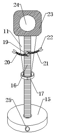
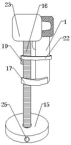
[0026] Refer to attached Figure 1-7 A fixed laser scanning device shown includes a scanner and a base, a cleaning mechanism and an up and down sliding mechanism. The scanner part includes an engine part 2 and a grip part 1, and the engine part 2 is fixed on the On the upper end of the grip part 1, five anti-skid finger rings 4 are arranged on the grip part 1, and each anti-skid finger ring 4 is a concave groove, and a scan button 3 is also arranged on the grip part 1, and the grip part 1 A circuit board is arranged inside, and an optical sensor and a control circuit are arranged on the circuit board, the optical sensor is electrically connected to the control circuit, a laser emitter and a reading lens are arranged...


PUM


Abstract

The invention discloses fixed type laser scanning equipment, including a scanner and a pedestal. The scanner includes an engine part and a holding part; the pedestal includes a sucker, a bendable pipe and an end part accommodating groove with an open end; the engine part consists of an engine head and a positioning seat, the bendable pipe is fixed on the sucker, a pad groove and a fixed disc are arranged on the bendable pipe, and the fixed disc is provided with bendable left enclasping arm and right enclasping arm; the engine head is arranged in the positioning seat, and includes a laser scanning window which is recessed inward, an upper end position of a scanning head of the laser scanning window is provided with a dust removing mechanism, and a front end side face of the laser scanning window is provided with a vertical sliding mechanisms. The fixed type laser scanning equipment reduces the failure rate, improves work efficiency, reduces loss, and has high feasibility; alleviates the extent of oppression and injury of a wrist, and can avoids occurrence of a phenomenon that after use, the scanner is placed at will for multiple times, and damage of the engine part is caused.

Description

technical field [0001] The invention relates to a scanning device, in particular to a fixed laser scanning device. Background technique [0002] The laser scanner is used to record the price, name, item number and other information of the commodity, and scan the barcode optically, which can quickly read the data, reduce a lot of time that originally required manual data entry, and save management and personnel costs. At present, the scanners for reading and barcodes can be divided into two types: fixed and handheld according to the operation mode. Among them, the handheld barcode scanner is a relatively economical and convenient device for reading barcodes. When the scanner reads the barcode, the positional relationship and angle between the scanning head and the barcode label are closely related to whether the barcode data can be read correctly and quickly. [0003] The scanning head of the laser scanner in the prior art is designed with a concave structure, and more dust ...

Claims


Application Information

Patent Timeline
Patent Type & Authority Patents(China)
IPC IPC(8): G06K7/10
Inventor 蔡群林杨彬汪劲松
Owner 山东亚泰医疗器械有限公司
Why Eureka
Try Eureka