A Novel Dielectric Dual-mode Bandpass Filter

A new type of dielectric and filter technology, applied in waveguide devices, electrical components, circuits, etc., can solve the problems of limited performance of methods and structures, difficult processing technology, and high processing difficulty, so as to achieve simple structure and reduce processing difficulty , The effect of solving processing problems

Inactive Publication Date: 2018-07-20
SOUTH CHINA UNIV OF TECH
View PDF5 Cites 0 Cited by
  • Summary
  • Abstract
  • Description
  • Claims
  • Application Information

AI Technical Summary

Problems solved by technology

The advantage of this structure is the use of multi-cavity structure and coaxial cavity, which improves the out-of-band suppression and suppresses the high-order mode, and the return loss is also very good. It is extremely difficult to perform corner cutting and digging operations.
[0007] To sum up, the published dielectric multimode filter articles or patent documents mostly involve cutting corners or digging holes on the dielectric block. The proposed method and structure processing technology are difficult and costly, and the published dielectric multimode Filter articles or patent documents mostly involve single-cavity dielectric multimode filters with complex structures, which are not suitable for the design of multi-order multi-cavity high-performance filters, and the performance of the proposed method and structure is limited.

Method used


Image

  • A Novel Dielectric Dual-mode Bandpass Filter
  • A Novel Dielectric Dual-mode Bandpass Filter
  • A Novel Dielectric Dual-mode Bandpass Filter

Examples


Embodiment 1

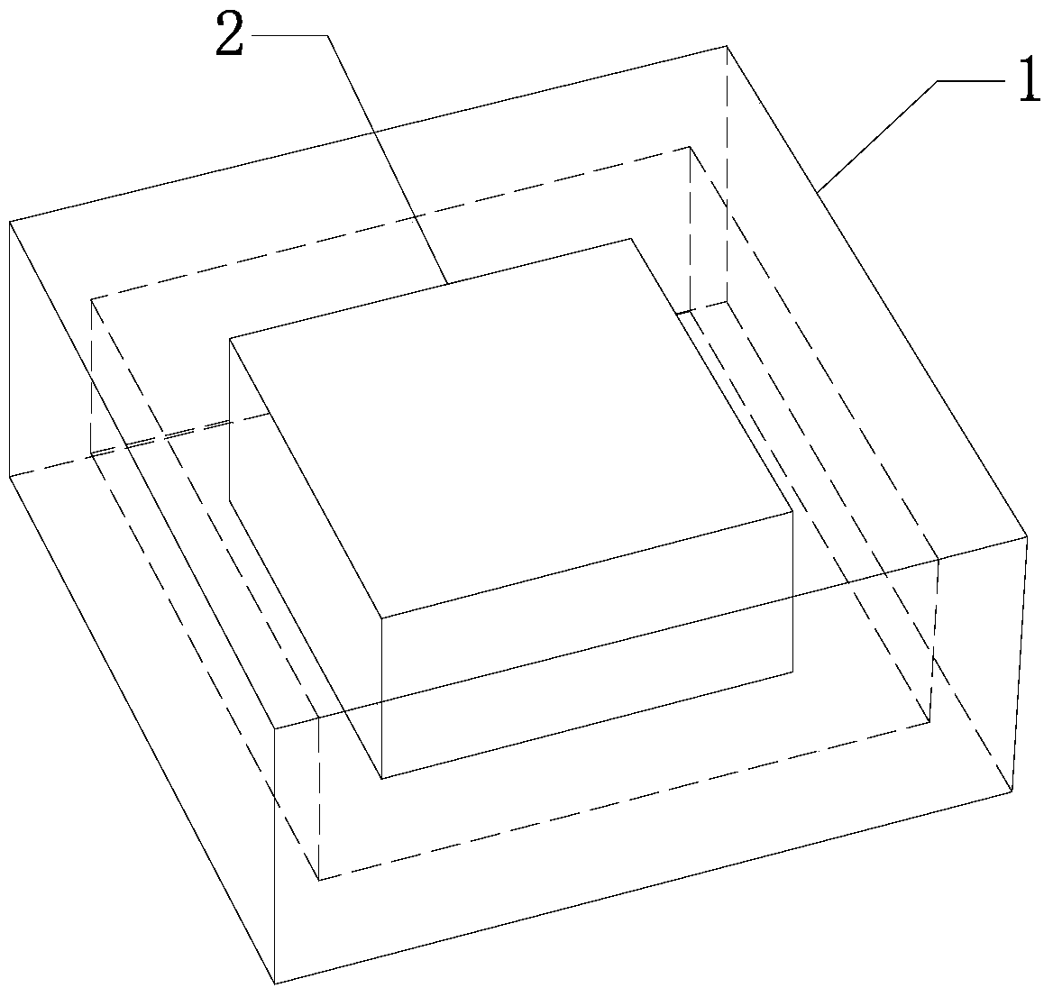
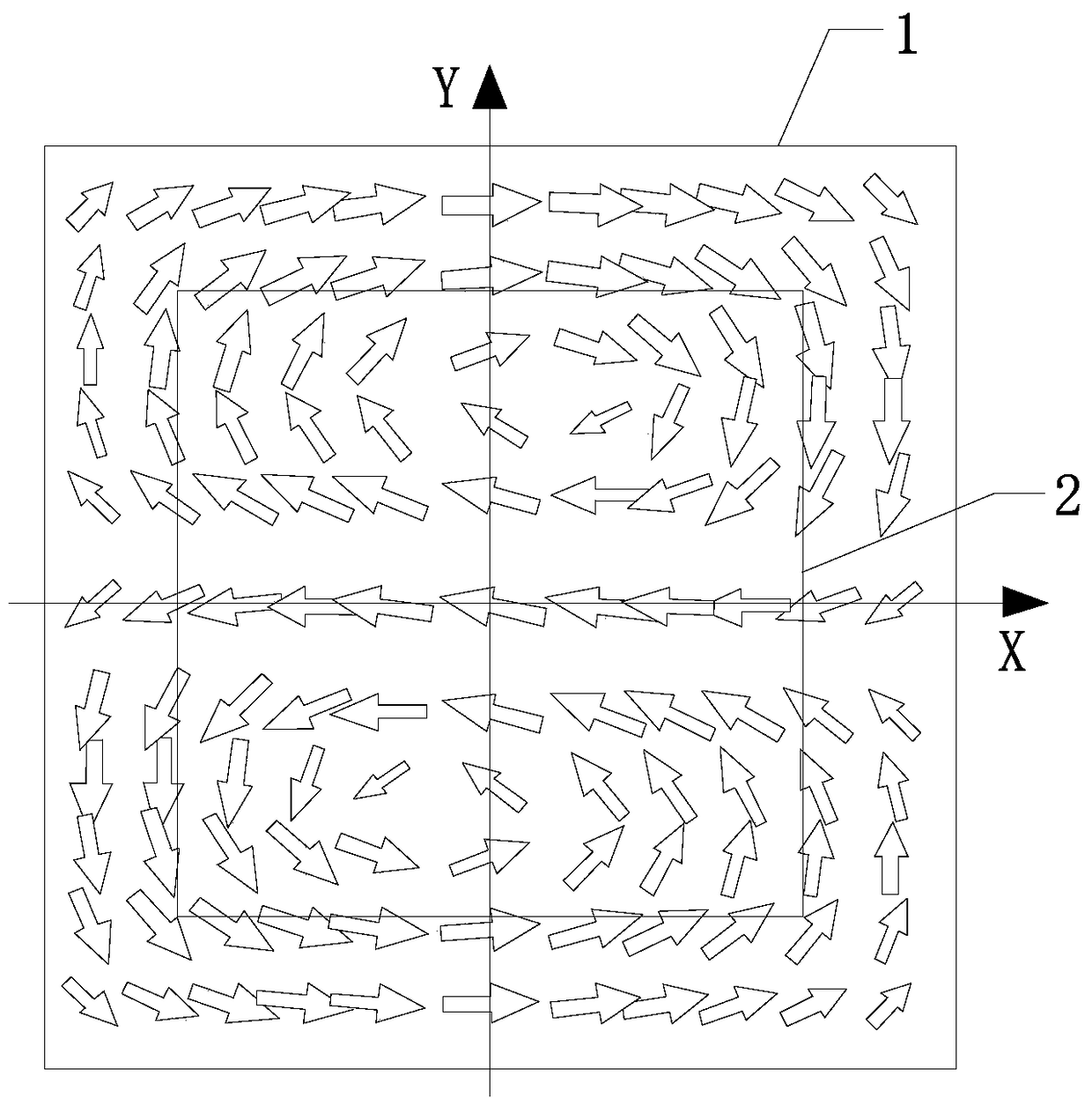
[0051] Such as figure 1 As shown, the dielectric dual-mode bandpass filter of this embodiment includes a cavity 1, the cavity 1 is a rectangular cavity with a size of 30mm*30mm*10mm, and a dielectric resonator is placed in the center of the cavity 1 2. The upper and lower ends of the dielectric resonator 2 are connected to the cavity 1, and the two degenerate modes (ie, resonance modes) adopted by the dielectric resonator 2 are called TM 120 Mode and TM 210 model;

[0052] The dielectric resonator 2 is a rectangular dielectric resonator with a size of 20mm*20mm*10mm and a relative permittivity of 21.4. In the example, the first metal screw 3 and the second metal screw 4 are inserted on the two outer sides (rear side and left side), and it can be seen that the transverse centerline of the first metal screw 3 and the transverse centerline of the second metal screw 4 are The line is vertical, the first metal screw 3 and the second metal screw 4 are used to control the resonanc...

Embodiment 2

[0065] This embodiment is based on the dielectric dual-mode bandpass filter of the two above-mentioned embodiment 1, utilizing such as Figure 11 (S in the figure represents the source end, L represents the load end, and 1 to 4 represent modes 1 to 4, respectively) The fourth-order linear topology shown in the figure can design a dual-cavity dielectric dual-mode bandpass filter based on a rectangular dielectric resonator. Such as Figure 12 As shown, the coupling mode of mode 2 and mode 3 is to achieve mode coupling through a closed metal ring, and the size of the closed metal ring (width inter-ring_w, height inter-ring_h) controls the size of the coupling coefficient, such as Figure 13 Shown; The S-parameter response of the dual-cavity dielectric dual-mode bandpass filter based on the rectangular dielectric resonator is as follows Figure 14 It can be seen from the figure that, in the bandwidth of 2624MHz-2692MHz, the passband return loss is below -15.6dB.

Embodiment 3

[0067] This embodiment is based on the dielectric dual-mode bandpass filter of four above-mentioned embodiment 1, utilizes such as Figure 15 (S in the figure represents the source end, L represents the load end, and 1 to 8 represent modes 1 to 8 respectively) The eighth-order linear topology shown in the figure can design a four-cavity dielectric dual-mode bandpass filter based on a rectangular dielectric resonator. Such as Figure 16 As shown, the coupling mode of mode 2 and mode 3, mode 4 and mode 5, mode 6 and mode 7 is to achieve mode coupling through a closed metal ring, and the size of the closed metal ring controls the size of the coupling coefficient. Based on the rectangular dielectric resonator The S-parameter response of the four-cavity dielectric dual-mode bandpass filter is as follows Figure 17 It can be seen from the figure that, in the bandwidth of 2634-2691MHz, the return loss of the passband is below -12.2dB.


PUM


Abstract

The invention discloses a novel dielectric dual-mode band-pass filter. A dielectric resonator is placed at a center position of a cavity, the upper end and the lower end of the dielectric resonator are connected with the cavity; a first metal bolt and a second metal bolt are inserted into the periphery of the dielectric resonator, a horizontal central line of the first metal bolt is vertical to that of the second metal bolt, the first metal bolt and the second metal bolt are used for controlling resonant frequencies of two resonant modes of the dielectric resonator; a closed metal ring is arranged at the crossing part of the magnetic fields of two resonant modes of the dielectric resonator, the closed metal ring is used for controlling the coupling strength between two resonant modes of the dielectric resonator. The dielectric dual-mode band-pass filter disclosed by the invention is simple in structure and convenient for implementation; the metal bolts and the closed metal ring are inserted into the periphery of the dielectric resonator so that the metal bolts and the closed metal ring can be used for realizing the frequency and coupling control.

Description

technical field [0001] The invention relates to a dielectric filter, in particular to a novel dielectric double-mode bandpass filter, which belongs to the technical field of microwave communication. Background technique [0002] Dielectric filters are widely used in satellite and cellular base station equipment due to their small size, good thermal stability, low insertion loss and high Q performance. Among them, the dielectric single-mode filter is widely used in the wireless communication industry because of its ease of manufacture and easy design of the coupling structure, while the dielectric multimode filter uses multiple resonance modes of the same dielectric resonator, which can provide more miniaturization advantages. This is extremely important for satellite systems. In practical applications, manufacturing and processing is a technical problem for dielectric multimode filters. In order to achieve coupling in the traditional dielectric multimode filter, it is nece...

Claims


Application Information

Patent Timeline
Patent Type & Authority Patents(China)
IPC IPC(8): H01P1/203
CPCH01P1/2039
Inventor 褚庆昕黄庆涛
Owner SOUTH CHINA UNIV OF TECH
Why Eureka
Try Eureka