Shooting method and shooting device
A technology for shooting devices and shooting components, which is applied to color signal processing circuits, TVs, color TV components, etc., and can solve problems such as not taking into account the shooting environment
- Summary
- Abstract
- Description
- Claims
- Application Information
AI Technical Summary
Problems solved by technology
Method used
Image
Examples
Embodiment 1
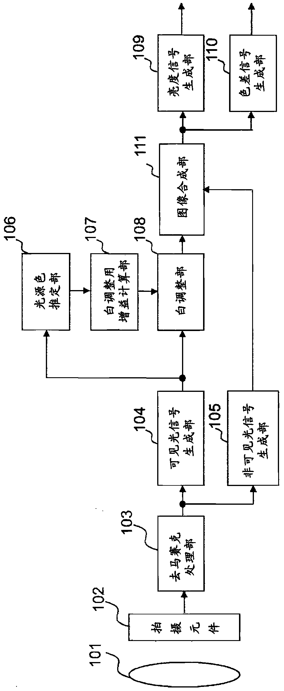
[0022] figure 1 It is a figure which shows an example of embodiment of this invention.
[0023] The imaging device of this embodiment has: a lens 101, which makes the visible light / non-visible light from the object to be photographed form an image at a predetermined focal length; Perform photoelectric conversion, and output a plurality of pixel signals corresponding to predetermined wavelength components; the demosaic processing unit 103 performs demosaic processing on the pixel signals from the imaging element 102; The pixel signal for the visible light component is subjected to arithmetic processing, thereby extracting the pixel signal (visible light signal) for the visible light component; pixel signal (invisible light signal); the light source color estimation unit 106 estimates the light source color based on the pixel signal from the visible light signal generation unit 104; Gain for performing white balance correction on the visible light signal output by the visible ...
Embodiment 2
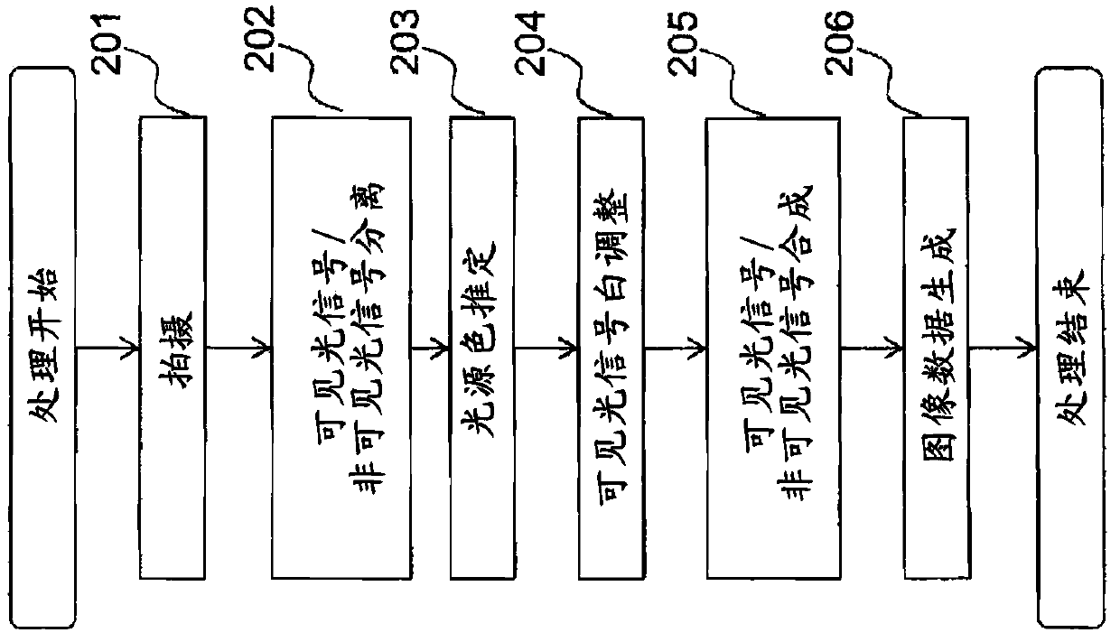
[0071] figure 2 It is a flowchart showing an example when the imaging method of the present invention is executed by a program.
[0072] This program is stored in a storage medium included in the imaging device or an information processing device capable of acquiring images, and is calculated by a control unit such as a CPU according to the program, and functions equivalent to those of the imaging device of the first embodiment can be realized by software.
[0073] In the imaging step 201 , an image of one frame is acquired using an imaging element capable of splitting and imaging light irradiated from a subject into predetermined wavelength components.
[0074] In the visible light signal / invisible light signal separation step 202, the image captured in the imaging step 201 is separated into an image signal corresponding to the visible light component (visible light signal) and an image signal corresponding to the invisible light component by performing signal processing. (...
Embodiment 3
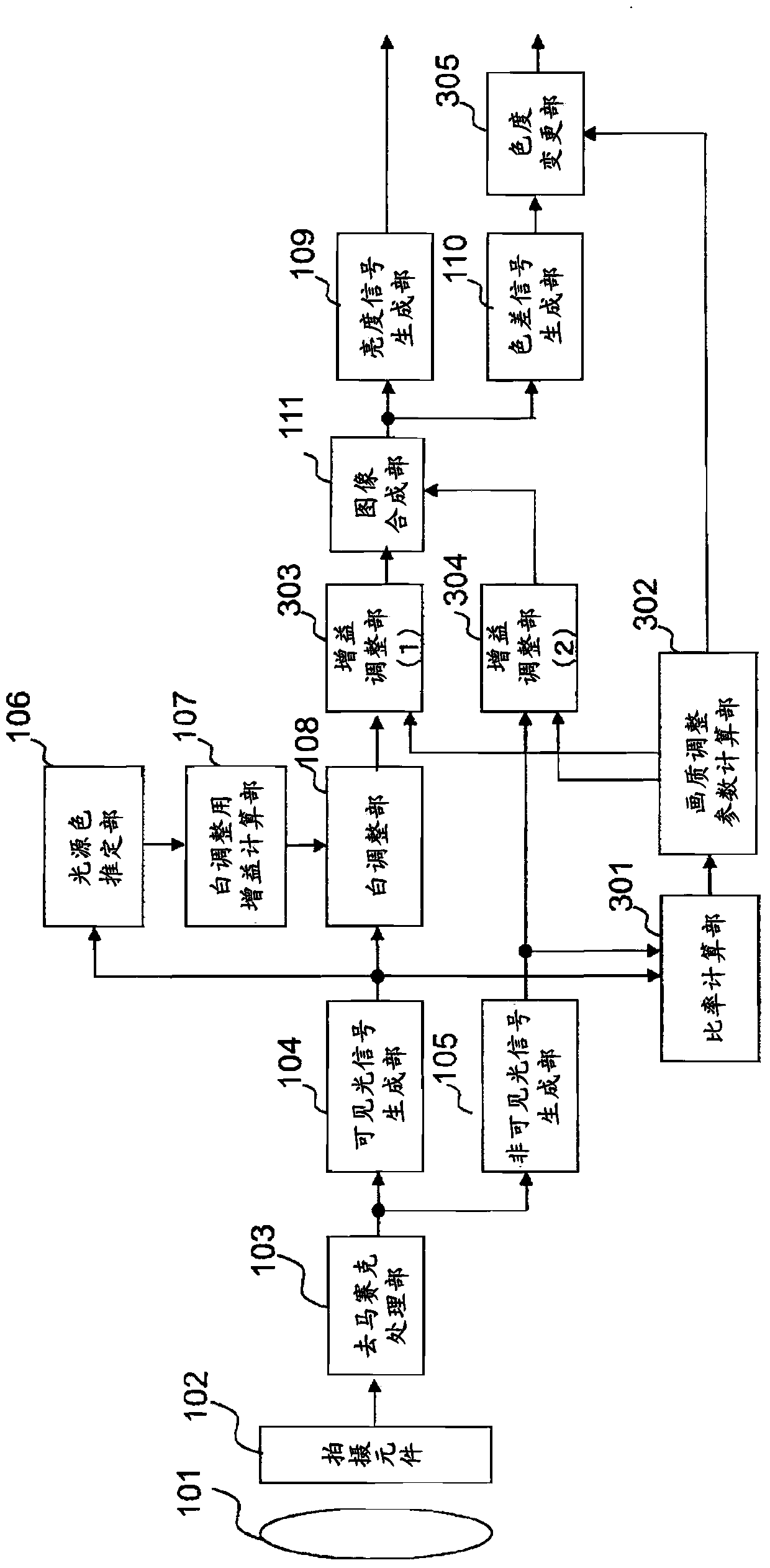
[0083] image 3 An example of embodiment of the present invention is shown. Compared with the structure of Embodiment 1, the imaging device of Embodiment 3 further includes: a ratio calculation unit 301 for calculating the ratio of each visible light signal output from the visible light signal generation unit 104 to the invisible light signal output from the invisible light signal generation unit 105 , and output the ratio information; the image quality adjustment parameter calculation unit 302, according to the ratio information output from the ratio calculation unit 301, calculates the visible light signal and the non-visible light signal for each white balance correction output from the white adjustment unit 108 The invisible light signal output by the generator 105 and the color difference signal output from the color difference signal generator 110 perform gain adjustment gain information and output it; information, to adjust the gain of the visible light signal after wh...
PUM
 Abstract
Description
Claims
Application Information
 - R&D
- Intellectual Property
- Life Sciences
- Materials
- Tech Scout
- Unparalleled Data Quality
- Higher Quality Content
- 60% Fewer Hallucinations
Browse by: Latest US Patents, China's latest patents, Technical Efficacy Thesaurus, Application Domain, Technology Topic, Popular Technical Reports.
© 2025 PatSnap. All rights reserved.Legal|Privacy policy|Modern Slavery Act Transparency Statement|Sitemap|About US| Contact US: help@patsnap.com


