
A cable reeling device

A technology of cable reels and turntables, which is applied in the directions of transportation and packaging, thin material handling, and delivery of filamentous materials. It can solve the problems of high labor intensity, different winding standards, and high costs, and achieve reduced production costs and better appearance of wire harnesses. Uniform and beautiful, improve the effect of bundling efficiency

Active Publication Date: 2019-06-04
蚌埠格识知识产权运营有限公司
View PDF7 Cites 0 Cited by
  • Summary
  • Abstract
  • Description
  • Claims
  • Application Information

AI Technical Summary

Problems solved by technology

Therefore, there are problems such as low efficiency, different winding standards, uneven appearance of the coiled cable drums, and the use of manual winding, which has high labor intensity, large investment, high cost, and is not suitable for large-scale production.

Method used


Image

  • A cable reeling device
  • A cable reeling device
  • A cable reeling device

Examples


Embodiment Construction

[0020] Below, the technical solution of the present invention will be described in detail through specific examples.

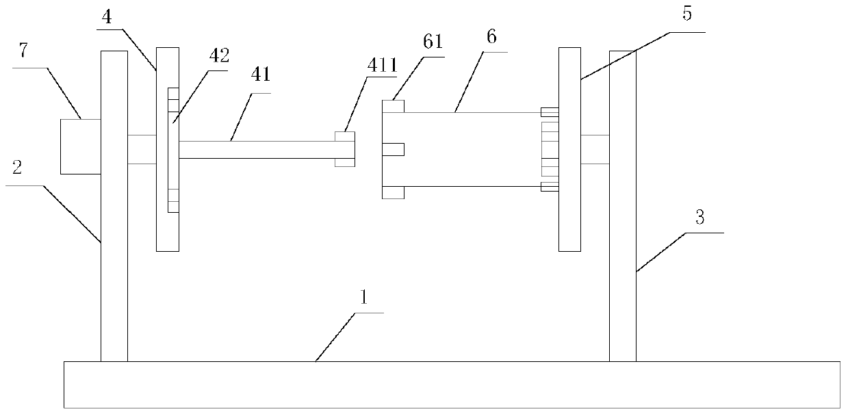
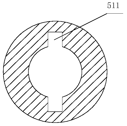
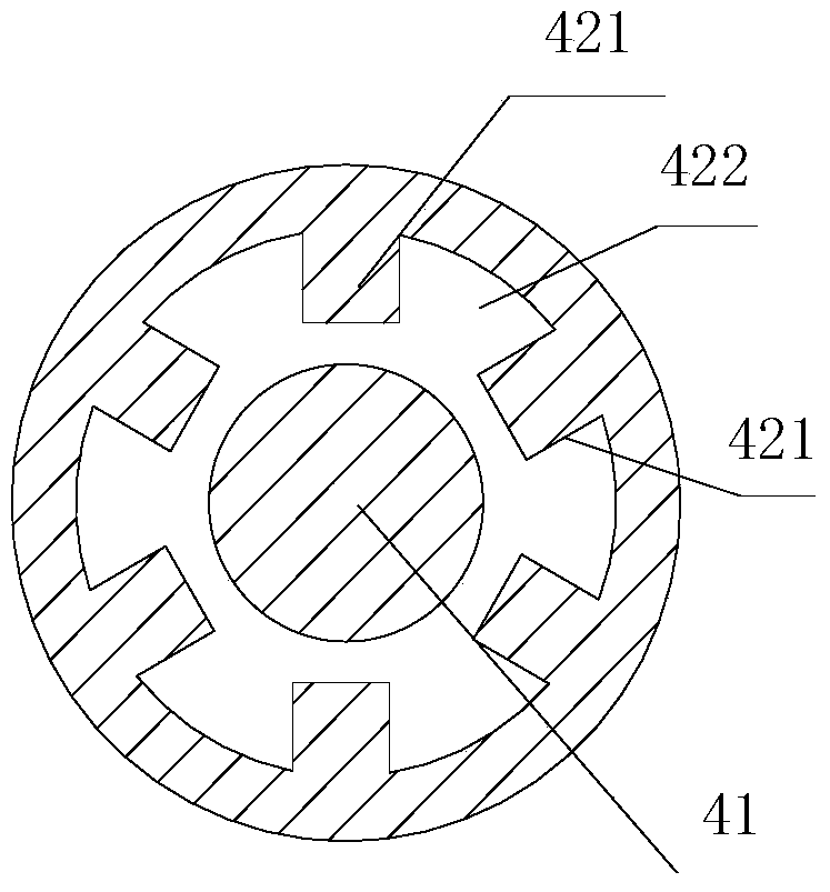
[0021] Such as Figure 1-4 as shown, figure 1 It is a structural schematic diagram of a cable coiling device proposed by the present invention; figure 2 It is a schematic diagram of the sleeve structure in a cable coiling device proposed by the present invention; image 3 It is a structural schematic diagram of a ring groove in a cable coiling device proposed by the present invention; Figure 4 It is a structural schematic diagram of a bobbin in a cable coiling device proposed by the present invention.

[0022] refer to Figure 1-4 , a cable coiling device proposed by an embodiment of the present invention, comprising: a mounting seat 1, a fixed bracket 2, a movable bracket 3, a driving turntable 4, a driven turntable 5, a bobbin 6 and a driving mechanism 7;

[0023] The fixed bracket 2 is fixedly installed on the mounting base 1;

[0024] The movable s...


PUM


Abstract

The invention discloses a cable take-up device which comprises a mounting base, a fixed support, a movable support, a driving rotary disc, a driven rotary disc, a winding reel and a driving mechanism. The fixed support is fixedly mounted on the mounting base. The movable support is movably mounted on the mounting base. The driving rotary disc is mounted on the fixed support and connected with the driving mechanism, the driving rotary disc is provided with a butt joint shaft and a ring groove, and the butt joint shaft is provided with first convex blocks. Second convex blocks are arranged on the inner circumferential surface of the ring groove, and a groove is formed between any two adjacent second convex blocks. The driven rotary disc is mounted on the movable support, the driven rotary disc is provided with a sleeve, and a clamping groove is formed in the sleeve. The winding reel is mounted on the driven rotary disc, and third convex blocks are arranged on the winding reel. Through the cable take-up device, a manual take-up mode is replaced, cables can be rapidly and automatically wound into cable coils of the unified specification, harnesses are uniform and attractive in appearance, the cable take-up and binding efficiency is greatly improved, and production cost is reduced.

Description

technical field [0001] The invention relates to the technical field of cable processing, in particular to a cable coiling device. Background technique [0002] In the cable production process, it is often necessary to wind the finished cable according to a certain size specification to form a cable reel, so as to facilitate storage, transportation and sales. At present, the cables in most cable production factories are wound and coiled by hand. Therefore, there are problems such as low efficiency, different winding standards, uneven appearance of the coiled cable drums, and manual winding, which has the problems of high labor intensity, large investment, high cost, and is not suitable for large-scale production. Contents of the invention [0003] Based on the technical problems in the above-mentioned background technology, the present invention proposes a cable coiling device to replace manual winding. [0004] The present invention proposes a cable coiling device, compr...

Claims


Application Information

Patent Timeline
Patent Type & Authority Patents(China)
IPC IPC(8): B65H54/553B65H67/04B65H75/10B65H75/18
CPCB65H54/553B65H67/0411B65H75/10B65H75/18
Inventor 谢安全黄承大
Owner 蚌埠格识知识产权运营有限公司
Learn More