Automatic forming method of volute spiral spring

An automatic forming and scroll spring technology, which is applied in the manufacture of springs from wires, other household appliances, household appliances, etc., can solve the problems of increasing manufacturing difficulty and manufacturing time, inflexible product replacement, and long development cycle, etc., so as to facilitate the use , prevent slipping, use flexible effects

Active Publication Date: 2020-03-10
常州泰瑞弹簧有限公司
View PDF12 Cites 0 Cited by
  • Summary
  • Abstract
  • Description
  • Claims
  • Application Information

AI Technical Summary

Problems solved by technology

[0003] At present, there are several ways to form the scroll spring spring for the tensioner: 1) The special machine developed by the enterprise itself: select a special mandrel according to the spring, and after the hooks at both ends are manually bent, they are formed on a special machine. The production efficiency of the forming method is low, the product development cycle is long, and the pitch needs to be controlled by a cloth belt or a steel bar; 2) Automatic forming machine: The forming principle is the same as that of a special machine, and a special mandrel and supporting tooling are also selected, but it can be One-time molding, high efficiency, this kind of molding method has the following disadvantages: a. Both the inner hook and the outer hook are formed by induction heating, which reduces the efficiency; b. The outer hook is mostly formed by stamping, and the replacement product is not enough Flexible; c. The wire needs to be quenched before use, which increases the difficulty and time of manufacturing
[0004] This shows that existing scroll spring automatic forming method still has many defects, needs to be improved urgently

Method used


Image

  • Automatic forming method of volute spiral spring

Examples


Embodiment Construction

[0020] The following will clearly and completely describe the technical solutions in the embodiments of the present invention with reference to the accompanying drawings in the embodiments of the present invention. Obviously, the described embodiments are only some, not all, embodiments of the present invention. Based on the embodiments of the present invention, all other embodiments obtained by persons of ordinary skill in the art without making creative efforts belong to the protection scope of the present invention.

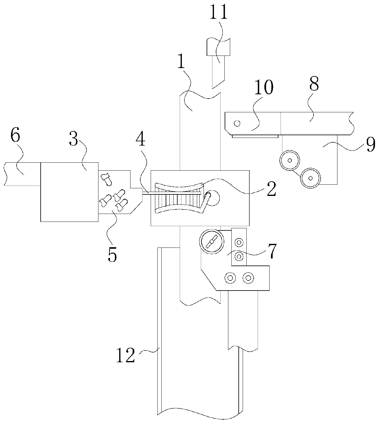
[0021] see figure 1 , the present invention provides a technical solution: a method for automatically forming a scroll spring, which specifically includes the following steps:

[0022] S1. Push the high-temperature heating furnace 2 forward through the first pneumatic device 1, and the winding device 3 pushes the wire 4 out of the cooling mechanism 5, and sticks the protruding part to the inner side of the high-temperature heating furnace 2 to heat the wire 4;...


PUM


Abstract

The invention discloses an automatic forming method of a volute spiral spring. The automatic forming method specifically comprises the following steps that S1, a high-temperature heating furnace is pushed to move forwards through a first pneumatic device, a wire rod is pushed out of a cooling mechanism by a winding device, and an extending part of the wire rod is adhered to the inner side of the high-temperature heating furnace to heat the wire rod; S2, the first pneumatic device drives the high-temperature heating furnace to return backwards, the winding device retracts the heated wire rod into the cooling mechanism for rapid cooling, and quenching is carried out; S3, a second pneumatic device pushes the winding device and the cooling mechanism to move right to a first curved line gauge,the winding device slowly pushes out the quenched wire rod, and the first curved line gauge moves upwards to perform inner-ring angle folding on the wire rod; and S4, a third pneumatic device pushes asecond curved line gauge to move to the left, the winding device accelerates to push the wire rod at a uniform speed, the first curved line gauge is used for performing rolling supporting on the bottom of the wire rod, spring wire rod winding is carried out through the space between two movable rollers of the second curved line gauge, and forming of a main body is completed.

Description

technical field [0001] The invention relates to the technical field of automatic forming equipment, in particular to an automatic forming method for a scroll spring. Background technique [0002] Spring is a mechanical part that uses elasticity to work. Parts made of elastic materials are deformed under the action of external force, and then return to their original shape after removing the external force. They are generally made of spring steel. The types of springs are complex and diverse, divided by shape, There are mainly coil springs, scroll springs, leaf springs, special-shaped springs, etc. According to the nature of the force, springs can be divided into tension springs, compression springs, torsion springs and bending springs, and can be divided into disc springs, ring springs, Plate springs, coil springs, truncated cone scroll springs, and torsion bar springs can be divided into cold coil springs and hot coil springs according to the production process. Ordinary cy...

Claims


Application Information

Patent Timeline
Patent Type & Authority Applications(China)
IPC IPC(8): B21F35/00
CPCB21F35/00
Inventor 杜强
Owner 常州泰瑞弹簧有限公司
Why Eureka
Try Eureka