Power matching method based on torque and rotation speed compound control for rotary drilling rig

A technology of rotary drilling rig and matching method, which is applied in the direction of mechanical control, engine control, drilling automatic control system, etc., can solve the problems of poor control, engine speed drop, control hysteresis, etc., and achieve practicability Strong, ensure stable operation, avoid flameout effect

Active Publication Date: 2016-03-16
徐州惠力机械制造有限公司
View PDF5 Cites 20 Cited by
  • Summary
  • Abstract
  • Description
  • Claims
  • Application Information

AI Technical Summary

Problems solved by technology

However, considering the inherent speed fluctuation characteristics of the engine itself, that is, during the normal operation of the engine, a deceleration or acceleration within a certain range is considered to be normal operation of the engine. Therefore, when applying the limit load control technology, all The set target value must be greater than the allowable speed drop value of the engine. Due to this specific limitation, control hysteresis occurs in the control process, so the phenomenon of engine speed drop is always not well controlled

Method used


Image

  • Power matching method based on torque and rotation speed compound control for rotary drilling rig
  • Power matching method based on torque and rotation speed compound control for rotary drilling rig
  • Power matching method based on torque and rotation speed compound control for rotary drilling rig

Examples


Embodiment Construction

[0028] The present invention will be described in further detail below in conjunction with the accompanying drawings.

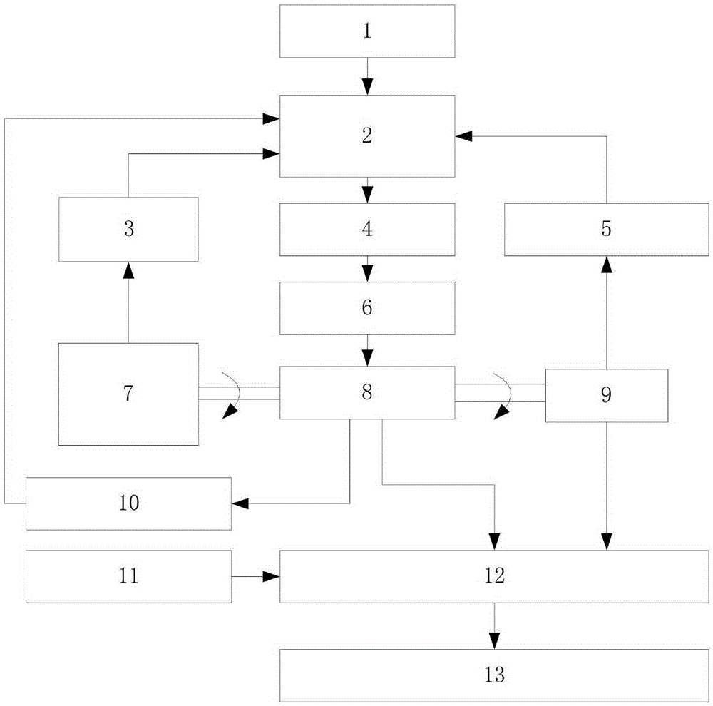
[0029] Such as figure 1 Shown is a structural block diagram of the hardware requirements of the rotary drilling rig power matching method based on the compound control of torque and speed. The hardware requirements include a speed setting button 1, which is connected to a controller 2 through a wire. Connect to engine ECU3 by CAN bus, described engine ECU3 is installed on the engine 7 as the control part of engine 7, engine 7 links to each other with main pump 8, auxiliary pump 9 through coupling, and described main pump 8 and described auxiliary pump 9 is equipped with a main pump pressure sensor 10 and an auxiliary pump pressure sensor 5, the main pump pressure sensor 10 and the auxiliary pump pressure sensor 5 are respectively connected to the input terminals of the controller 2 through wires, and the output of the controller 2 The terminal is connected t...


PUM


Abstract

The invention discloses a power matching method based on torque and rotation speed compound control for a rotary drilling rig. The power matching method comprises the following steps: calculating target current according to pressure of a primary pump and a secondary pump and set target torque percentage; setting a speed drop value during interconversion of a rotation speed regulating module and a torque regulating module; when a real-time speed drop value of an engine is smaller than a set value, adopting the torque regulating module to carry out compensation regulation on target current; when the real-time speed drop value of the engine is greater than the set value, adopting the rotation speed regulating module to carry out compensation regulation on the target current; and outputting a final current value to an inverse proportion pressure-reducing valve to control a displacement regulator to change displacement of the primary pump, thereby controlling input power of the primary pump in real time. The power matching method is simple, reliable and high in practicability, has the characteristics of rotation speed control rapidity and torque control predictability, can effectively avoid severe speed drop of the engine, avoids a shut-down phenomenon, improves operation efficiency of the rotary drilling rig and guarantees operation stability of a control system.

Description

technical field [0001] The invention relates to a power matching method of a rotary drilling rig based on compound control of torque and rotational speed, which is applied to the power matching control of a hydraulic pump and an engine of the rotary drilling rig. Background technique [0002] Rotary drilling rig is a high-tech product in the field of pile machinery technology. It is a large-scale foundation construction machinery equipment suitable for hole-forming operations in building foundation engineering. It is widely used in foundation construction projects such as municipal construction, highway bridges, and high-rise buildings. With the development of the market, users have higher and higher requirements for the performance of rotary drilling rigs, not only requiring them to be able to adapt to complex working conditions, but also to have energy-saving features. However, improving the performance of rotary drilling rigs often comes down to improving the control char...

Claims


Application Information

Patent Timeline
Patent Type & Authority Applications(China)
IPC IPC(8): F02D29/04E21B44/00
CPCE21B44/00F02D29/04F02D2250/24F02D2700/07
Inventor 高英杰刘凯磊韩建立蒲泽川田竞春武强
Owner 徐州惠力机械制造有限公司
Why Eureka
Try Eureka