Garbage incinerator

A technology of waste incinerator and incinerator, which is applied in the directions of incinerator, combustion method, combustion type, etc., can solve the problems of energy waste and incineration heat utilization, etc., and achieve good energy saving, high energy utilization rate and high safety. Effect

Inactive Publication Date: 2016-03-16
鹤山市凤台菱精密铸造有限公司
View PDF7 Cites 6 Cited by
  • Summary
  • Abstract
  • Description
  • Claims
  • Application Information

AI Technical Summary

Problems solved by technology

However, the existing incineration equipment cannot make good use

Method used


Image

  • Garbage incinerator

Examples


Embodiment Construction

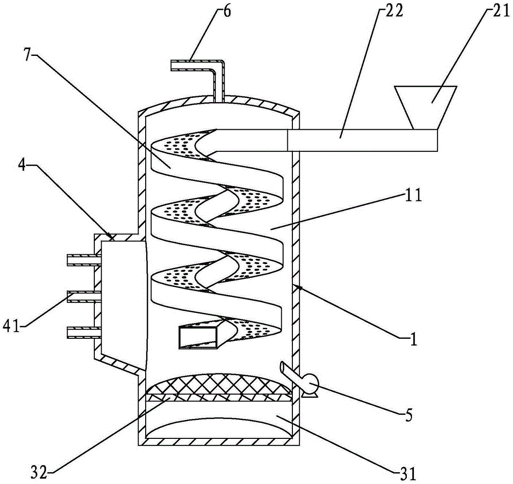
[0018] Such as figure 1 As shown, the garbage incinerator includes a furnace body 1 provided with an incineration chamber 11, a feeding part arranged on the upper part of the incineration chamber 11, a discharge part arranged at the bottom of the incineration chamber 11, and a fire storage chamber arranged on the side of the furnace body 1 4. There is a communication part between the fire storage chamber 4 and the incineration chamber 11, and the lower part of the furnace body 1 is provided with a fan 5 whose air outlet faces the communication part. The fan 5 blows part of the flame in the incineration chamber 11 into the fire storage chamber 4. Since this part of the flame is relatively violent and difficult to control, the fire storage chamber 4 can be used as a buffer device to convert it into a controllable flame, and then from the fire storage chamber Some fire outlets 41 on the 4 output.

[0019] The feeding part includes a feeding hopper 21 and a screw conveying device...


PUM


Abstract

The invention discloses a garbage incinerator. The garbage incinerator comprises an incinerator body with an incineration chamber, a feeding part arranged at the upper portion of the incineration chamber, a discharging part arranged at the bottom of the incineration chamber, and a fire accumulating chamber arranged on the side face of the incinerator body. A communication part is arranged between the fire accumulating chamber and the incineration chamber. A draught fan with an air outlet facing the communication part is arranged at the lower portion of the incinerator body. The garbage incinerator has the beneficial effects of being high in safety, good in energy saving performance, high in energy utilization rate and the like.

Description

technical field [0001] The invention relates to the field of garbage incineration, in particular to a garbage incinerator. Background technique [0002] Garbage disposal has always been a major environmental issue of concern all over the world. Traditional waste disposal methods mainly include landfill and incineration. Landfilling will take up a lot of valuable land resources and pollute the environment at the same time, so this simple treatment method is basically no longer used. Compared with landfill treatment, through incineration, the volume of garbage can be greatly reduced in a short period of time, coupled with the increasingly mature control technology for harmful gases, incineration technology has become a kind of garbage commonly used at home and abroad. processing technology. However, the existing incineration equipment cannot make good use of the heat generated by incineration, resulting in waste of energy. Contents of the invention [0003] The present i...

Claims


Application Information

Patent Timeline
IPC IPC(8): F23G5/00F23G5/44
Inventor 范凤招
Owner 鹤山市凤台菱精密铸造有限公司
Why Eureka
Try Eureka