Thermal column structure

A thermal column and capillary structure technology, applied in the field of heat dissipation, can solve problems such as low efficiency, achieve the effect of improving heat dissipation and prolonging service life

Inactive Publication Date: 2016-03-16
JIANGSU HONGLI PHOTOELECTRIC TECH
View PDF6 Cites 0 Cited by
  • Summary
  • Abstract
  • Description
  • Claims
  • Application Information

AI Technical Summary

Problems solved by technology

Capillary structures are generally provided on the inner wall of the existing heat column, and the capillary force of the capillary structure is used to accelerate the reflux speed of co

Method used


Image

  • Thermal column structure

Examples


Embodiment 1

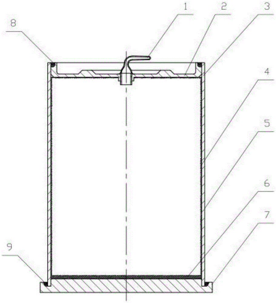
[0014] Such as figure 1 As shown, a thermal column structure includes a capillary 1, a column body 5, an upper cover 2 and a bottom plate 7 which are arranged on the upper and lower ends of the column body 5 and are adapted thereto, and the upper cover 2 and the bottom plate 7 are sealed with the column body Cooperate. A through hole is opened in the middle part of the upper cover, the lower end of the capillary 1 is welded on the through hole, and the upper end of the capillary is closed to form a vacuum seal inside the cylinder.

[0015] The capillary structure includes an upper capillary structure 3, a middle capillary structure 4 and a bottom capillary structure 6 arranged along the upper cover 2, the cylinder 5 and the inner wall of the bottom plate 7 respectively, and the upper capillary structure 3, the middle capillary structure 4 and the bottom capillary structure 6 connected to form an integrated heat dissipation structure.

[0016] The cylinder 5 is a hollow cylin...


PUM

PropertyMeasurementUnit
Thicknessaaaaaaaaaa
Thicknessaaaaaaaaaa

Abstract

The invention discloses a thermal column structure. The thermal column structure comprises a column body, a capillary pipe and a capillary structure arranged in the column body; an upper cover and a baseplate matched with the column body are arranged at the upper and lower ends of the column body, and are tightly matched with the column body; a through hole is formed in the middle part of the upper cover; the lower end of the capillary pipe is welded on the through hole, and the upper end of the capillary pipe is closed, so that the internal of the column body is sealed in vacuum; a proper amount of liquid working medium is filled in the column body sealed in vacuum; the capillary structure comprises an upper capillary structure, a middle capillary structure and a bottom capillary structure arranged along the upper cover, the column body and the inner wall of the baseplate; and the upper capillary structure, the middle capillary structure and the bottom capillary structure are connected to form an integral cooling structure for quickly dissipating heat, so that the cooling effect is further improved, and the service life of the product is largely prolonged.

Description

technical field [0001] The invention relates to heat dissipation technology, in particular to a heat column structure. Background technique [0002] The thermal column absorbs a large amount of heat through the boiling or evaporation of the liquid working medium to generate steam, and the steam condenses on the wall of the thermal column to release a large amount of latent heat of vaporization to realize heat exchange. The heat column is widely used in the fields of LED lamps, electronic components and other heat dissipation. The bottom of the heat column continuously absorbs the heat from the surface of the LED chip or electronic components. Distributed to the external environment or matching heat dissipation equipment through the wall of the condensing tube, thereby effectively controlling the temperature of the LED chip or electronic components, ensuring the stability and reliability of its work. Capillary structures are generally provided on the inner wall of the existi...

Claims


Application Information

Patent Timeline
IPC IPC(8): F28D15/04
CPCF28D15/046
Inventor 吕文卿胡循亮张长亮唐黎
Owner JIANGSU HONGLI PHOTOELECTRIC TECH
Why Eureka
Try Eureka