Method for monitoring winding device

A technology of winding device and winding shaft, applied in the direction of winding strips, general control system, electrical testing/monitoring, etc., can solve problems such as wrong operation of winding device, wrong operating parameters, etc., and achieve the effect of improving reliability

Inactive Publication Date: 2016-03-16
WINDMOELLER & HOELSCHER GMBH
View PDF12 Cites 1 Cited by
  • Summary
  • Abstract
  • Description
  • Claims
  • Application Information

AI Technical Summary

Problems solved by technology

This leads, especially in hazardous situations, to decisions that may be based on incorrect operating parameters
It is also possible that in this way insufficient or poorly trained operators carry out erroneous operations on the winding device

Method used


Image

  • Method for monitoring winding device
  • Method for monitoring winding device
  • Method for monitoring winding device

Examples


Embodiment Construction

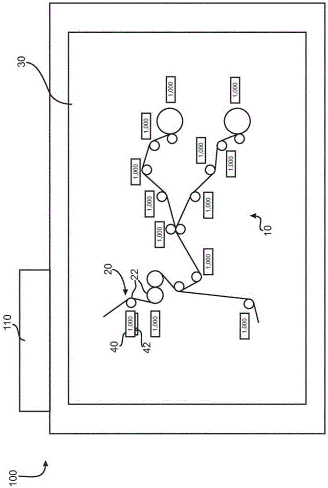
[0037] exist figure 1 An embodiment of the monitoring device 100 according to the invention is schematically shown in . The monitoring device has a display device 30 and a monitoring unit 110 . A computing unit for executing a computer program product, which controls the individual method steps, is located in the monitoring unit 110 .

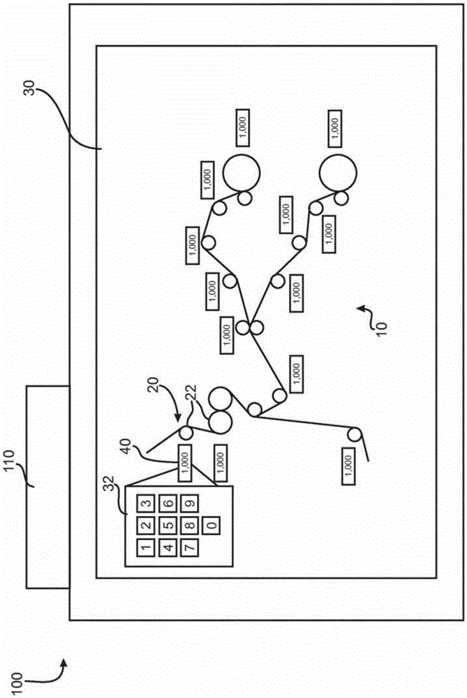
[0038] as in figure 1 As can be clearly seen in , a schematic illustration of the winding device 10 can be seen on the display device 30 , wherein the display device is designed here as a touch-sensitive display, ie a touch screen. The winding device has a plurality of functional units 20 , which are all designed here as transport rollers 22 . The stretching process of the film can be seen schematically between the individual transport rollers 22 . The winding takes place clockwise for both winding bobbins.

[0039] also in figure 1 It can be clearly seen in FIG. 1 that operating parameters 40 are displayed in the spatial vicinity of a pl...


PUM


Abstract

The invention relates to a method for monitoring a winding device (10), comprising the following steps: displaying a schematic illustration of functional units (20) of the winding device (10) on a display device (30), detecting at least one operating parameter (40) of at least one functional unit (20) of the winding device (10), displaying the at least one detected operating parameter (40) on the display device (30) next to the schematic illustration of the associated functional unit (20).

Description

technical field [0001] The invention relates to a method for monitoring a winding device and a monitoring device for monitoring a winding device. Background technique [0002] It is basically known to wind films, for example, onto winding bobbins by means of winding devices. Film rolls are thus produced which can be widely used at the respective customer. Winding takes place in a winding device. In order to be able to monitor the winding, usually at least one display device or a monitoring device with such a display device is provided. The monitoring takes place here by displaying the corresponding operating parameters of the individual functional units on the display device. [0003] A disadvantage of the known monitoring device and of the known method for monitoring a winding device is that the monitoring is not very intuitive or takes place in a flawed manner. In this way, corresponding information is contained on different planes of the display. Accordingly, intensi...

Claims


Application Information

Patent Timeline
Patent Type & Authority Applications(China)
IPC IPC(8): B65H26/00B65H18/00G05B23/02
CPCB65H26/00B65H18/00B65H2551/18B65H2551/20G05B19/409B65H18/08G05B15/02
Inventor 迈克尔·奥斯滕多夫弗兰克·霍夫曼
Owner WINDMOELLER & HOELSCHER GMBH
Why Eureka
Try Eureka