

Stirring device for calcium carbonate
A stirring device, calcium carbonate technology, applied in mixers with rotary stirring devices, calcium carbonate/strontium/barium, mixer accessories, etc. Strong continuous working ability, reasonable design, and the effect of improving production efficiency
Inactive Publication Date: 2016-03-23
宜兴天力化工纳米科技有限公司
View PDF2 Cites 3 Cited by
- Summary
- Abstract
- Description
- Claims
- Application Information
AI Technical Summary
Problems solved by technology
The traditional stirring device is equipped with a heating block at the bottom or on the side wall. However, due to the large internal space of the shell, the heating device is simply installed on the side wall or bottom, which may cause the local temperature in the device to be too low, which is not conducive to cycle production.
Method used
View moreImage
Smart ImageViewing Examples

Examples
Embodiment Construction
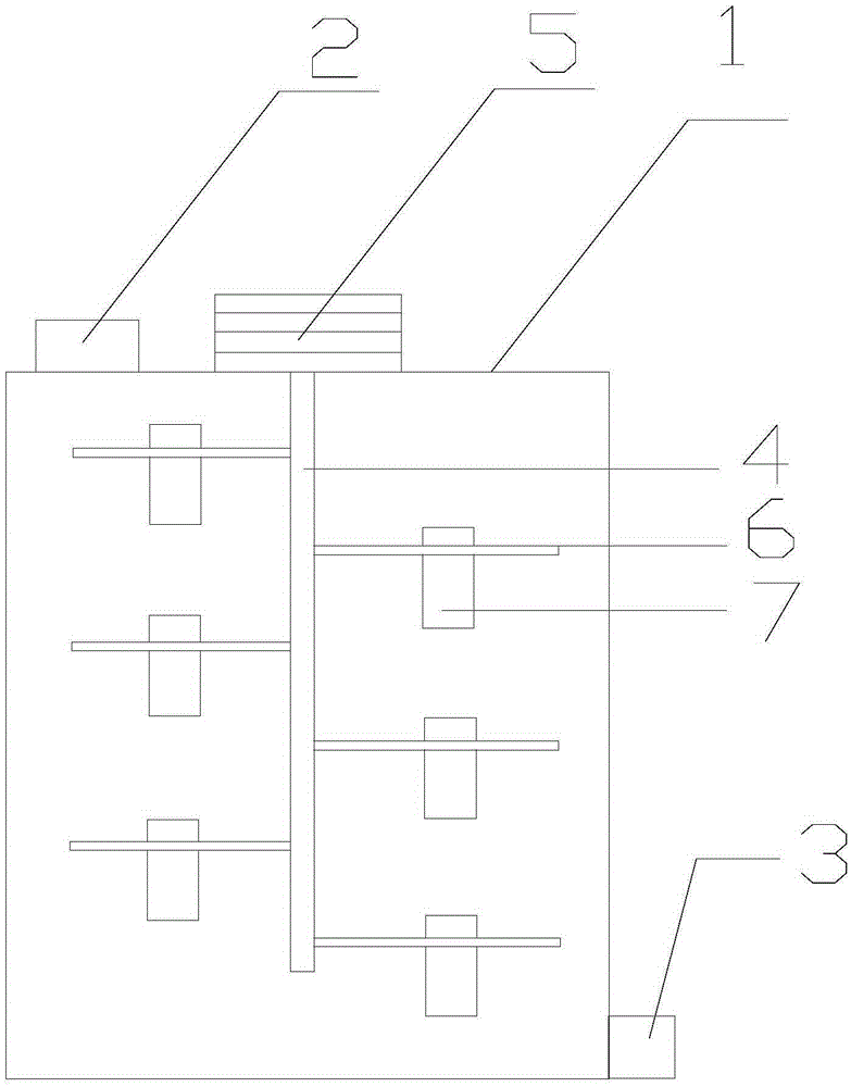
[0009] like figure 1 A kind of stirrer that the present invention provides as shown is used for calcium carbonate, comprises housing 1, and housing 1 top is provided with feed inlet 2, the bottom is provided with discharge outlet 3, is provided with stirring bar 4, in housing 1, And the stirring rod 4 is connected to the electric head 5 outside the housing 1; the stirring rod 4 is provided with stirring blades 6 alternately, and the heating device 7 is fixed on the stirring blade 6; the heating device 7 is an electric heating device covered with a metal shell. Wire; the stirring rod 4 is hollow, and the electric wire of the heating device 7 is connected to the power supply equipment outside the housing 1 through the stirring rod 4.
Login to View More PUM
 Abstract
The invention discloses a stirring device for calcium carbonate. The stirring device comprises a shell. A feed port is formed in the top end of the shell. A discharge port is formed in the bottom of the shell. A stirring stick is arranged in the shell and connected with an electric head outside the shell. Stirring blades are arranged on the stirring stick in a staggered mode. Heating devices are fixed to the stirring blades. The stirring device is reasonable in design and high in continuous working capacity; by fixing the heating devices to the stirring blades, it is ensured that heating is uniform in the device, and production efficiency is improved.
Description
technical field [0001] The invention belongs to the field of chemical industry, in particular to a stirring device for calcium carbonate. Background technique [0002] Calcium carbonate is usually reacted and synthesized in a reactor, and taken out after the temperature is lowered. Since a certain temperature and stirring are required during the synthesis, the requirements for the device are relatively high. The traditional stirring device is equipped with a heating block at the bottom or on the side wall. However, due to the large internal space of the shell, simply installing the heating device on the side wall or bottom may cause the local temperature in the device to be too low, which is not conducive to cycle production. Contents of the invention [0003] Purpose of the invention: the purpose of the invention is to provide a kind of stirring device for calcium carbonate for the deficiencies in the prior art. [0004] Technical solution: In order to achieve the above...
Claims
Login to View More Application Information
Patent Timeline
 Patent Type & AuthorityApplications(China)
IPC IPC(8): B01J19/18B01F7/18B01F15/06C01F11/18
CPCB01J19/0013B01J19/0066B01J19/18C01F11/18B01J2219/185B01J2219/00135B01F27/071B01F27/112B01F27/21B01F27/90B01F35/95B01F2035/99
Inventor薛汉华
Owner宜兴天力化工纳米科技有限公司