Inertia cone crusher

A cone crusher and inertial technology, which is applied to grain processing and other directions, can solve the problems of destroying the bearing bush's supporting effect on the moving cone and the main shaft, the moving cone being easily detached from the bearing bush, and the two contact surfaces being easily damaged, etc. The effect of strong reliability and convenient operation

Inactive Publication Date: 2016-03-23
王修彦
5 Cites 6 Cited by

AI-Extracted Technical Summary

Problems solved by technology

[0002] At present, most inertial cone crushers use a motor to directly drive the moving cone shaft, and the cone is driven to do a swinging motion under the action of the counterweight to crush the material. When subjected to a large extrusion stress, the moving cone is easy to break away from the bearing bush, or ...

Method used

Please refer to Fig. 1, the present invention provides a kind of technical scheme: a kind of inertial cone crusher, comprises underframe 1, underframe 1 lower end intermediate position is provided with belt drive 2, and belt drive 2 top is provided with movable cone 9. The shaft of the movable cone 9 is installed in cooperation with the shaft sleeve 11. The side of the shaft sleeve 11 is fixed with a vibration exciter 4. The vibration exciter 4 is driven by the traditional device 2 to vibrate, and the vibration is transmitted to the dynamic cone 9 through the shaft sleeve 11. There is no rigid connection between the cone 9 and the power unit 2, which prevents damage to the axis of the movable cone 9 when being squeezed by overload. The cone head of the movable cone 9 is supported by the movable cone support 10, and the movable cone support 10 and the movable cone 9 Spherical tiles 6 are installed between the lower sides of the cone heads, and a lining plate 7 is installed on the upper side of the cone head of the movable cone 9. A fixed cone 8 is arranged above the m...

Abstract

The invention discloses an inertia cone crusher. The inertia cone crusher comprises a bottom frame. A belt transmission device is arranged in the middle of the lower end of the bottom frame, a movable cone is arranged above the belt transmission device, a movable cone shaft is installed in cooperation with a shaft sleeve, a vibration exciter is fixedly installed on the side face of the shaft sleeve, a movable cone head is supported by a movable cone supporting base, a spherical bush is installed between the movable cone supporting base and the lower side face of the movable cone head in cooperation, a liner plate is installed on the inner side conical face of a fixed cone in cooperation, a shell is located above the bottom frame, a rubber pad is installed between the shell and the bottom frame, and the movable cone supporting base makes contact with the shell. No rigid connection exists between the movable cone and a transmission mechanism, damage to the movable cone caused by overload of extrusion stress is prevented, counter-acting force borne by the spherical bush can be counteracted by the shell and the rubber pad together to a certain extent, the work environment of the spherical bush is greatly improved, and the whole device is simple in structure, convenient to operate, high in efficiency and high in work reliability.

Application Domain

Grain treatments

Technology Topic

EngineeringWorking environment +5

Image

  • Inertia cone crusher

Examples

  • Experimental program(1)

Example Embodiment

[0012] The technical solutions in the embodiments of the present invention will be clearly and completely described below in conjunction with the accompanying drawings in the embodiments of the present invention. Obviously, the described embodiments are only a part of the embodiments of the present invention, rather than all the embodiments. Based on the embodiments of the present invention, all other embodiments obtained by those of ordinary skill in the art without creative work shall fall within the protection scope of the present invention.
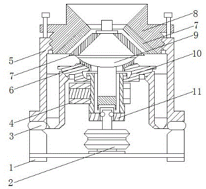
[0013] See figure 1 , The present invention provides a technical solution: an inertial cone crusher comprising a base frame 1, a belt transmission device 2 is provided at the middle position of the lower end of the base frame 1, and a movable cone 9 is provided above the belt transmission device 2, and the movable cone 9 shaft and The shaft sleeve 11 is matched and installed, and the side of the shaft sleeve 11 is fixedly installed with a vibration exciter 4. The traditional device 2 drives the vibration exciter 4 to vibrate, and the vibration is transmitted to the moving cone 9, the moving cone 9 and the power device 2 through the shaft sleeve 11. There is no rigid connection between them, which prevents damage to the shaft of the movable cone 9 when subjected to overloading. The cone head of the movable cone 9 is supported by the movable cone support 10, and the movable cone support 10 is matched with the lower side of the cone 9 A spherical tile 6 is installed, and the upper side of the cone head of the moving cone 9 is fitted with a lining plate 7. A fixed cone 8 is arranged above the moving cone 9. The cone angle of the moving cone 9 is equal to the cone angle of the fixed cone 8, and the belt drive device 2 The axis of the rotating shaft coincides with the axis of the fixed cone 8. A liner 7 is fitted on the inner cone surface of the fixed cone 8 to prevent excessive wear of the fixed cone 8. The fixed cone 8 has a funnel shape, and the inner surface of the fixed cone 8 is opposite to the movable cone 9 Installed, and the outer surface of the fixed cone 8 is connected with the housing 5 through a threaded pair. A feeding device is installed on the small end of the fixed cone 8. The housing 5 is located above the base frame 1, and a rubber pad 3 is installed between the housing 5 and the base frame 1. , And the bottom surface of the movable cone support 10 is in contact with the housing 5. When the movable cone 9 is working, the movable cone support 10 can offset a certain reaction force with the help of the housing 5 and the rubber pad 3, which greatly improves the working environment of the spherical tile 6. The rapid wear of the spherical tile 6 is prevented, and the entire device has a simple structure, convenient operation, high efficiency and strong working reliability.
[0014] Although the embodiments of the present invention have been shown and described, those of ordinary skill in the art can understand that various changes, modifications, and substitutions can be made to these embodiments without departing from the principle and spirit of the present invention. And variations, the scope of the present invention is defined by the appended claims and their equivalents.

PUM

no PUM

Description & Claims & Application Information

We can also present the details of the Description, Claims and Application information to help users get a comprehensive understanding of the technical details of the patent, such as background art, summary of invention, brief description of drawings, description of embodiments, and other original content. On the other hand, users can also determine the specific scope of protection of the technology through the list of claims; as well as understand the changes in the life cycle of the technology with the presentation of the patent timeline. Login to view more.

Similar technology patents

Method for side air supply of driving face of large-diameter deep vertical shaft

ActiveCN103939122Aimprove working environmentImprove the thermal environment
Owner:CHINA UNIV OF MINING & TECH

Classification and recommendation of technical efficacy words

  • improve working environment
  • Simple structure

Automatic boom road-header space pose detection system and measurement method thereof

ActiveCN105241444AImprove working environmentImprove tunneling efficiency
Owner:TAIYUAN INST OF CHINA COAL TECH & ENG GROUP +2

Super-large diameter shield cutterhead system used in hard-soft heterogeneous ground

PendingCN106907158Aimprove working environmentImprove stability and adaptability
Owner:CHINA RAILWAY TUNNEL GROUP CO LTD +1

Queuing system for waiting room in medical institution

InactiveCN101315711Aimprove working environmentImprove patient comfort
Owner:SHENZHEN LANDWIND IND

Screed vibrator and paver

Owner:SANY HEAVY IND CO LTD (CN)
Why Eureka
Try Eureka