Roll gap adjusting mechanism of rolling mill

A technology for adjusting mechanism and roll gap, applied in the direction of metal rolling mill stand, metal rolling stand, metal rolling, etc., can solve the problems of increasing steel rolling cost, harsh working conditions of elastic colloid, short service life, etc.

Inactive Publication Date: 2016-03-23
CHONGQING MAITUO TECH CO LTD
View PDF7 Cites 4 Cited by
  • Summary
  • Abstract
  • Description
  • Claims
  • Application Information

AI Technical Summary

Problems solved by technology

[0004] However, as we all know, the working conditions of elastic colloids are relatively harsh, and they are not suitable for high and low temperatures. At the same time, due to the effect of

Method used


Image

  • Roll gap adjusting mechanism of rolling mill
  • Roll gap adjusting mechanism of rolling mill
  • Roll gap adjusting mechanism of rolling mill

Examples


Embodiment Construction

[0042] The core of the present invention is to provide a rolling mill roll gap adjustment mechanism to achieve the simultaneous adjustment of roll gaps and guide roll gaps, and to have a stable, reliable and long service life preload balance system to ensure the smooth progress of steel rolling operations Purpose.

[0043] In order to enable those skilled in the art to better understand the solution of the present invention, the present invention will be further described in detail below in conjunction with the accompanying drawings and specific embodiments.

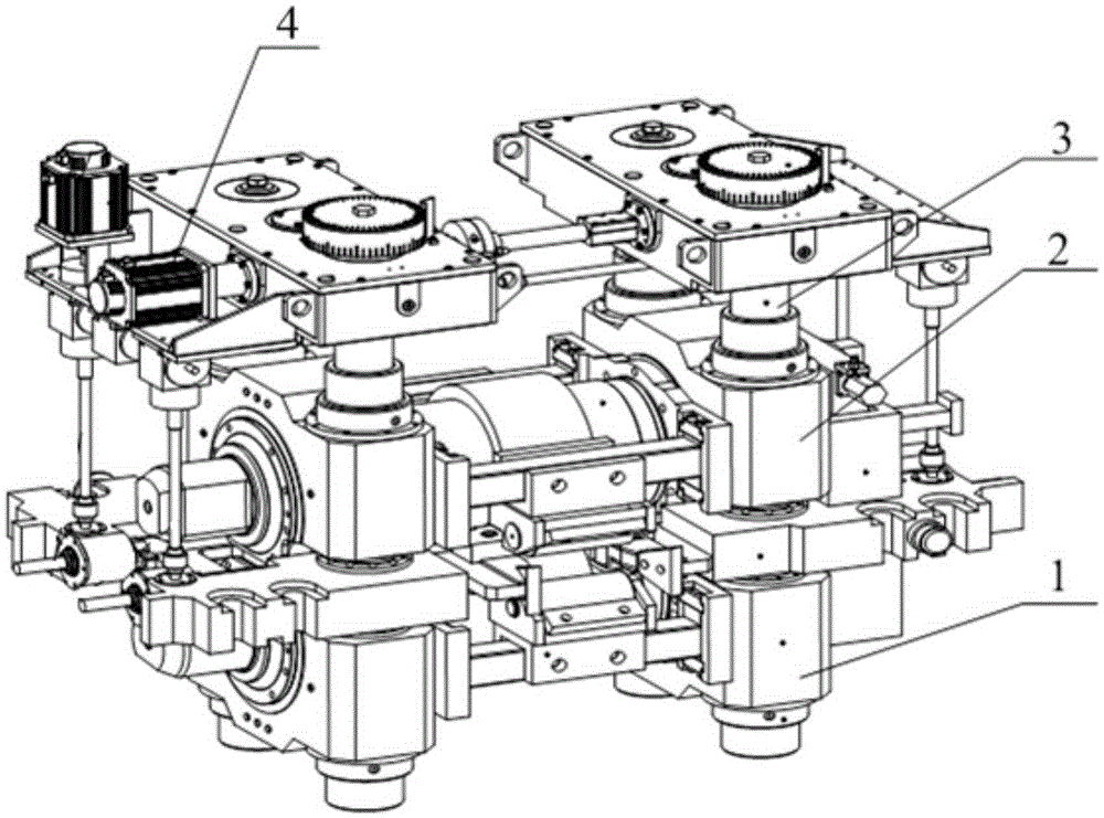
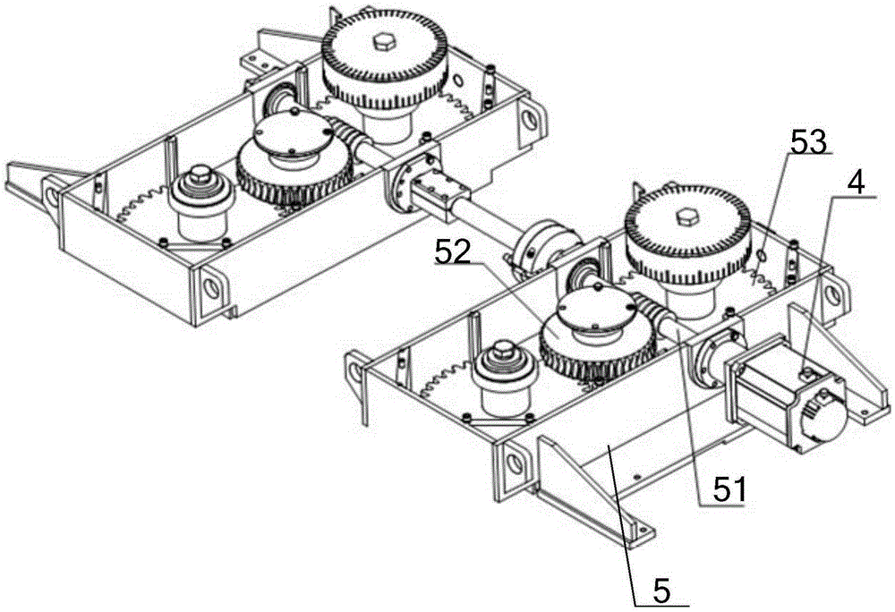
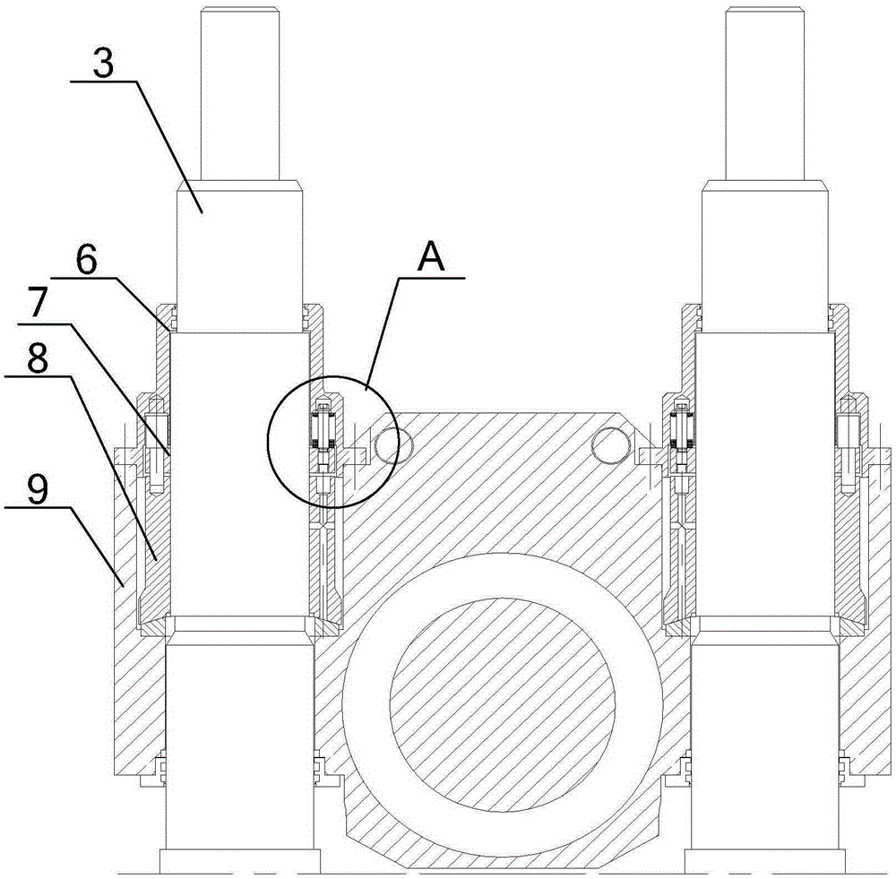
[0044] Please refer to Figure 1-Figure 4 , figure 1 It is a schematic diagram of the overall structure of the rolling mill disclosed in the embodiment of the present invention, figure 2 It is a schematic diagram of the drive mechanism disclosed in the embodiment of the present invention, image 3 It is a schematic cross-sectional view of the connection structure between the screw and the bearing seat on one side of ...


PUM


Abstract

The invention relates to a roll gap adjusting mechanism of a rolling mill. The roll gap adjusting mechanism comprises a lower guide roll bracket, a lower guide roll, an upper guide roll bracket and an upper guide roll, wherein the two ends of the lower guide roll bracket are correspondingly connected with bottom end bearing bases; the lower guide roll is rotationally arranged on the lower guide roll bracket; the two ends of the upper guide roll bracket are correspondingly connected with upper end bearing bases; the upper guide roll bracket is corresponding to the lower guide roll bracket; the upper guide roll is rotationally arranged on the upper guide roll bracket; the bearing bases are in threaded connection with lead screws through inner-layer sleeves; the bottom ends of outer-layer sleeves are butted against the inner-layer sleeves through spherical surface sleeve pads; balance nuts are connected to the lead screws through threads; through covers coat the lead screws, and the lower ends of the through covers are fixedly connected with the outer-layer sleeves; and pretightening springs are arranged between the through covers and the balance nuts. As the guide roll brackets are arranged on the bearing bases, a guide roll gap can be synchronously adjusted when adjusting a mill roll gap; and the pretightening springs apply an upward elastic force to the through covers, and the elastic force is transferred to the outer-layer sleeves through the through covers and transferred to the inner-layer sleeves through the outer-layer sleeves so as to upwards lift the inner-layer sleeves to eliminate a thread gap.

Description

technical field [0001] The invention relates to the technical field of metallurgical manufacturing, in particular to a rolling mill roll gap adjustment mechanism. Background technique [0002] A rolling mill is required in the steel rolling process. Usually, the steel passes through the guide rollers of the guide device and then enters the rolls for rolling. In the prior art, when it is necessary to process rolled pieces of other specifications, the rolling mill generally adjusts the gap between the rolls through the screw slider mechanism to meet the production requirements, but the existing guide device cannot adjust the gap between the guide rolls. For adjustment, it is necessary to replace the guide device of the corresponding model, which is cumbersome to operate and affects production efficiency. [0003] In addition, due to the large rolling force in the steel rolling process, the thread gap generated when the screw thread is matched must be considered, otherwise the...

Claims


Application Information

Patent Timeline
IPC IPC(8): B21B31/24B21B39/14
CPCB21B31/24B21B39/14
Inventor 唐辉
Owner CHONGQING MAITUO TECH CO LTD
Why Eureka
Try Eureka