Eureka AIR delivers breakthrough ideas for toughest innovation challenges, trusted by R&D personnel around the world.

Bending device capable of adjusting pipe angle

A bending device and angle technology, applied in the field of pipe angle adjustable bending devices, can solve the problems of increasing the labor intensity of workers, increasing the difficulty of construction, low production efficiency, etc., and achieving simple structure, reduced labor intensity, production Efficient effect

Active Publication Date: 2016-03-23
HENAN SINOKO CRANES
View PDF7 Cites 4 Cited by
  • Summary
  • Abstract
  • Description
  • Claims
  • Application Information

AI Technical Summary

Problems solved by technology

[0002] During the processing of the crane, it is necessary to protect the cable lines of the electrical part of the crane through the pipe, which requires bending the wire pipe. However, in the existing production process, the workers mainly use hand tools to bend the pipe. , the process of this kind of pipe bending is very complicated, which increases the labor intensity of workers, and the production efficiency is low. In addition, for pipes with large diameter pipes, manual pipe bending is very difficult. In addition, the bending process In the process, due to the needs of various processes, the angles of pipe bending are different, which requires workers to be very precise in the bending process, increasing the difficulty of construction

Method used


Image

  • Bending device capable of adjusting pipe angle
  • Bending device capable of adjusting pipe angle
  • Bending device capable of adjusting pipe angle

Examples


Embodiment 1

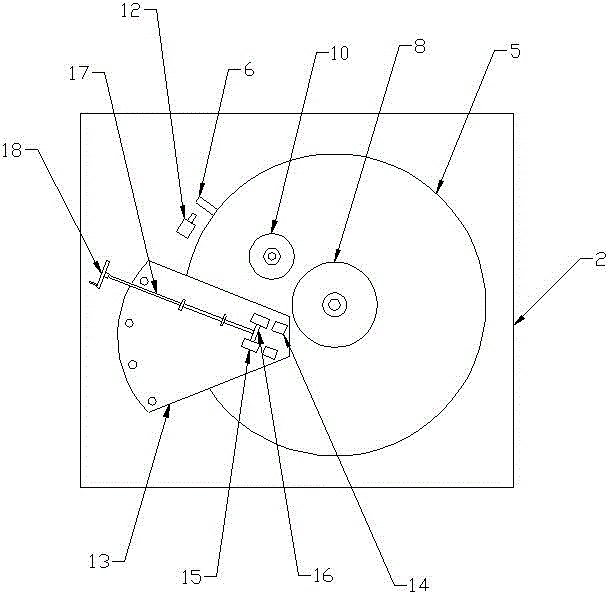
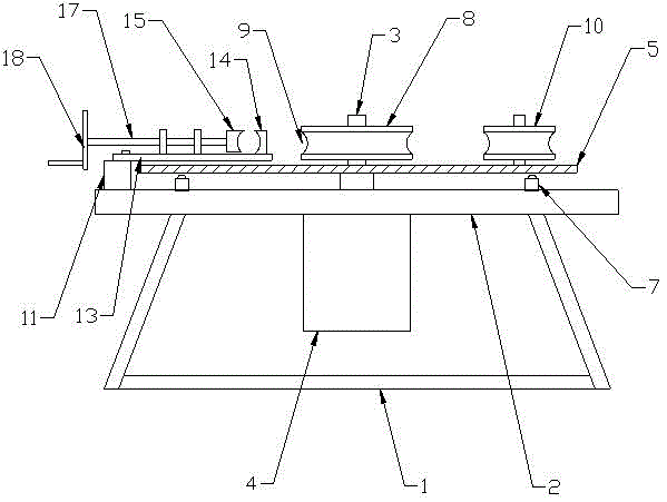
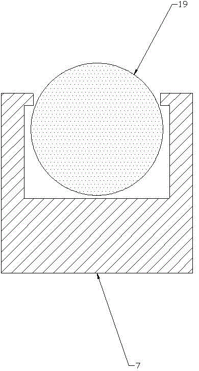
[0019] Such as Figure 1-4 As shown, a pipe angle adjustable bending device includes a bracket 1, the upper part of the bracket 1 is provided with a fixed plate 2, and the central lower part of the fixed plate 2 is provided with a rotating shaft 3, and the rotating shaft 3 The lower end of the rotating shaft 3 is connected with a rotating motor 4, the rotating motor 4 is connected with an angle sensor, the angle sensor is connected with a controller, the upper part of the rotating shaft 3 is fixedly connected with a rotating disk 5, and the outer surface of the rotating disk 5 Limit stoppers 6 are arranged on the edge, and the lower part of the outer circumference of the rotating disk 5 is provided with a support seat 7. The upper end of the rotating shaft 3 is connected with a bending main wheel 8 through a bearing, and the outer edge of the bending main wheel 8 is provided with an arc Groove 9, the side of the upper surface of the rotating disc 5 is provided with a bending s...

Embodiment 2

[0022] Such as Figure 1-4 As shown, a pipe angle adjustable bending device includes a bracket 1, the upper part of the bracket 1 is provided with a fixed plate 2, and the central lower part of the fixed plate 2 is provided with a rotating shaft 3, and the rotating shaft 3 The lower end of the rotating shaft 3 is connected with a rotating motor 4, the rotating motor 4 is connected with an angle sensor, the angle sensor is connected with a controller, the upper part of the rotating shaft 3 is fixedly connected with a rotating disk 5, and the outer surface of the rotating disk 5 Limit stoppers 6 are arranged on the edge, and the lower part of the outer circumference of the rotating disk 5 is provided with a support seat 7. The upper end of the rotating shaft 3 is connected with a bending main wheel 8 through a bearing, and the outer edge of the bending main wheel 8 is provided with an arc Groove 9, the side of the upper surface of the rotating disc 5 is provided with a bending s...


PUM


Abstract

The invention relates to a bending device capable of adjusting the pipe angle. The bending device comprises a supporting frame. A fixing plate is arranged at the upper portion of the supporting frame. A rotary shaft is arranged at the lower portion of the center of the fixing plate, the lower end of the rotary shaft is connected with a rotating motor, and the rotating motor is connected with an angle sensor. A rotary disc is fixedly connected with the upper portion of the rotary shaft. A limiting blocking piece is arranged at the outer edge of the rotary disc, and a supporting base is arranged at the lower portion of the rotary disc. A main bending wheel is connected with the upper end of the rotary shaft, and an arc groove is formed in the outer edge of the main bending wheel. An auxiliary bending wheel is arranged on one side of the upper surface of the rotary disc. A fixing base and a reset switch are arranged on the upper surface of the fixing plate. A supporting plate is arranged on the upper surface of the fixing base. Pipe fixing bases A and pipe fixing bases B are arranged at the end of the upper surface of the supporting plate. A connecting rod is arranged between the pipe fixing bases B and connected with a threaded rod, and a hand wheel is arranged at one end of the threaded rod. The bending device capable of adjusting the pipe angle has the beneficial effects of being simple in structure, reasonable in design and high in production efficiency, reducing the labor intensity of workers and facilitating adjustment of the bending angle.

Description

technical field [0001] The invention belongs to the technical field of pipe bending equipment, in particular to a pipe angle adjustable bending device. Background technique [0002] During the processing of the crane, it is necessary to protect the cable lines of the electrical part of the crane through the pipe, which requires bending the wire pipe. However, in the existing production process, the workers mainly use hand tools to bend the pipe. , the process of this kind of pipe bending is very complicated, which increases the labor intensity of workers, and the production efficiency is low. In addition, for pipes with large diameter pipes, manual pipe bending is very difficult. In addition, the bending process Among them, due to the needs of various processes, the angles of pipe bending are different, which requires workers to be very precise in the bending process, which increases the difficulty of construction. Contents of the invention [0003] The object of the pres...

Claims


Application Information

Patent Timeline
Patent Type & Authority Applications(China)
IPC IPC(8): B21D7/08
CPCB21D7/08
Inventor 郭仕超王积贤崔丽胡哲涛
Owner HENAN SINOKO CRANES
Why Eureka
Eureka Blog
Learn More