Annular locking mechanism used for wire harnesses

A locking mechanism and ring-shaped technology, applied in the direction of flexible and slender elements, packaging, transportation and packaging, etc., can solve the problems of lack of comprehensive utilization, unreasonable operation, high production cost, etc., and achieve strong practicability and structure The effect of stability, firmness and simple structure

Inactive Publication Date: 2016-03-23
ANHUI ANLAN MOLD
View PDF10 Cites 3 Cited by
  • Summary
  • Abstract
  • Description
  • Claims
  • Application Information

AI Technical Summary

Problems solved by technology

[0002] Cable ties, as the name suggests, are straps for binding things. They are designed with a backstop function and can only be tied tighter and tighter. There are also detachable cable ties, which are divided into metal cable ties and plastic cable ties. They are often used in cables of mechanical and electrical products, computers, electronics, etc. Products and automobile wiring harnesses are fixed. The traditional cable tie is a plastic strip with clips. Although this type of cable tie is convenient to use, due to different specifications and aesthetic requirements, after the cable tie is installed, the redundant clips will be removed. The rack is cut into sections, and when the traditional cable ties are used, they generally stop retreating, so there is a lot of waste in actual materials. At this stage, there are cable ties with a retractable function on the market, but their actual operation is not satisfactory. Unreasonable, high production cost, not comprehensively utilized

Method used


Image

  • Annular locking mechanism used for wire harnesses
  • Annular locking mechanism used for wire harnesses
  • Annular locking mechanism used for wire harnesses

Examples


Embodiment Construction

[0016] In order to make the technical means, creative features, objectives and effects of the present invention easy to understand, the present invention will be further explained below with reference to specific embodiments and drawings.

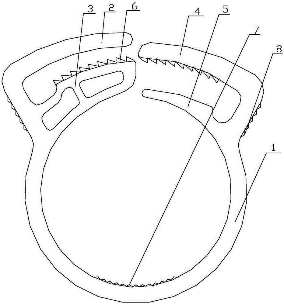
[0017] Such as figure 1 As shown, an annular locking mechanism for a wire harness, the main body is a half-closed ring 1, one end of the ring 1 is provided with an upper splint 2 and a lower clamping plate 3, and the other end of the ring 1 is provided with an upper The clamping gear plate 4 and the lower clamping plate 5, the upper clamping gear plate 4 and the lower clamping gear plate 3 are provided with clamping teeth 6 with opposite tooth shapes, and the upper clamping gear plate 3 is arranged between the upper clamping plate 2 and the lower clamping gear plate 3. The lower clamping gear plate 3 is set between the upper clamping gear plate 4 and the lower clamping plate 5. After this setting, when the wire harness needs to be locked, first...


PUM


Abstract

The invention discloses an annular locking mechanism used for wire harnesses and relates to a fixing device. A body of the annular locking mechanism is a semi-closed circular ring. An upper clamping plate and a lower latch plate are arranged at one end of the circular ring. An upper latch plate and a lower clamping plate are arranged at the other end of the circular ring. Latches which are opposite in tooth form are arranged in the upper latch plate and the lower latch plate respectively. The upper latch plate is arranged between the upper clamping plate and the lower latch plate. The lower latch plate is arranged between the upper latch plate and the lower clamping plate. The annular locking mechanism has the beneficial effects that the design is novel, the structure is simple, and a traditional plastic ribbon is improved to be in an annular shape; a normal locking function of the annular locking mechanism is guaranteed, and meanwhile a ring receding effect is achieved; material waste is avoided, using is convenient and fast, the structure is stable and firm, the practicability is high, and application and popularization are facilitated.

Description

Technical field [0001] The invention relates to a fixing device, in particular to an annular locking mechanism for a wire harness. Background technique [0002] Cable tie, as the name implies, is a strap for binding things. It is designed with a stop function and can only be tied tighter and tighter. There are also detachable cable ties. They are divided into metal ties and plastic ties. They are commonly used in electrical cables, computers, and electronics. For fixing products and automobile wiring harnesses, the traditional cable tie is a plastic strip provided with teeth. Although this type of cable tie is convenient to use, due to the different specifications and aesthetic requirements, after the installation of the cable tie, the extra card will be removed. Rack is cut, and traditional cable ties are generally used to stop back. Therefore, there is a lot of waste in actual materials. At this stage, there are retractable cable ties on the market, but the actual operation is ...

Claims


Application Information

Patent Timeline
Patent Type & Authority Applications(China)
IPC IPC(8): B65D63/10
CPCB65D63/1018B65D2563/107
Inventor 王玉宝詹金珠陈士坤张如宏崔伟东
Owner ANHUI ANLAN MOLD
Why Eureka
Try Eureka