
An Interferometric Microwave Radiation Clock Scanning Imaging Device

A technology of scanning imaging and microwave radiation, applied in the field of microwave remote sensing, to reduce system complexity, save costs, and improve imaging quality

Active Publication Date: 2018-06-15
中科深瞳(北京)科技有限公司
View PDF9 Cites 1 Cited by
  • Summary
  • Abstract
  • Description
  • Claims
  • Application Information

AI Technical Summary

Problems solved by technology

[0005] The purpose of the present invention is to overcome the difficulties of the dual-degree-of-freedom antenna array rotary scanning technology, solve the difficult problems of the clock scanning turntable control mechanism and signal transmission, and meet the needs of the clock scanning interferometric microwave radiometer for practical application. The present invention proposes an interferometric Microwave Radiation Timing and Scanning Imaging Device

Method used


Image

  • An Interferometric Microwave Radiation Clock Scanning Imaging Device
  • An Interferometric Microwave Radiation Clock Scanning Imaging Device
  • An Interferometric Microwave Radiation Clock Scanning Imaging Device

Examples


Embodiment Construction

[0043] The present invention will be further described below in conjunction with the accompanying drawings and specific embodiments.

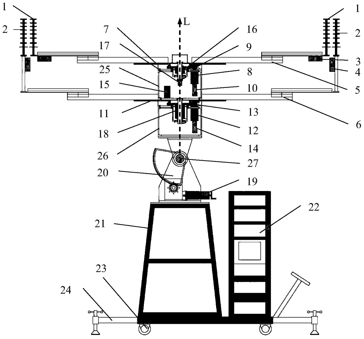
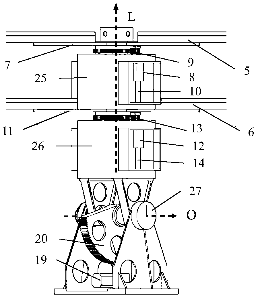
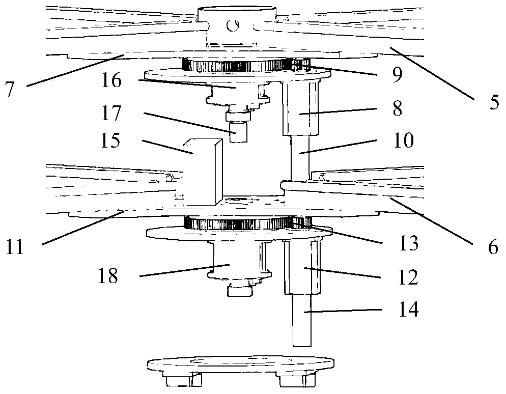
[0044] The interference microwave radiation timing and scanning imaging device provided by the invention, such as figure 1 As shown, the 8 unit antennas for receiving external electromagnetic wave signals are divided into 2 groups of 4, namely the minute hand unit antenna 1 and the second hand unit antenna 2. The 8 unit antennas can work in any radio frequency band. The four minute-hand unit antennas 1 are respectively installed on the tops of the four minute-hand antenna support arms 5 . Four second hand unit antennas 2 are installed on the top of the second hand antenna support arm 6 . The second hand unit antenna 2 is located outside the minute hand unit antenna 1 and is in the same plane. The installation orientation of all element antennas is parallel to the central axis L.

[0045] The minute hand radio frequency receiver 3 and the secon...


PUM


Abstract

The invention relates to an interferometic microwave radiometer clock scanning imaging device comprising unit antennas, radio-frequency receivers, antenna arms, conductive slip rings, a radio-frequency rotary joint, a digital plate and clock module, a three-axis turntable, a turntable bracket and a numerical control processing cabinet. The imaging device is characterized in that the unit antennas are mounted on first-stage and second-stage mounting surfaces of the three-axis turntable, double-speed rotary scanning around the same center rotating shaft in the same plane can be realized, and signal transmission between the radio-frequency receivers and the digital plate and clock module and the numerical control processing cabinet is carried out through the slip rings and the radio-frequency rotary joint. The device has the following beneficial effects: the double-speed rotary scanning work mode of the unit antennas is realized; the transmission problem of signals is solved; and a two-stage superimposed independent-control turntable mechanism is adopted, and the digital plate and clock module is placed on the second-stage bearing surface of rotation.

Description

technical field [0001] The invention belongs to the technical field of microwave remote sensing, and in particular relates to a passive microwave radiometer imaging device, in particular to a microwave radiometer scanning imaging device which utilizes an interferometric synthetic aperture imaging technology to realize high spatial resolution. Background technique [0002] Microwave radiometer is an important detection instrument in the field of microwave remote sensing. It obtains the radiation brightness temperature of the target by receiving the natural radiation of the target, and then inverts some specific physical parameters of the target. Microwave radiometers are widely used in remote sensing fields such as the atmosphere, ocean, vegetation, and soil. At the same time, they are also popularized in emerging fields such as environmental investigation, hidden target detection, and non-destructive security inspection. [0003] A major disadvantage of microwave radiometers...

Claims


Application Information

Patent Timeline
Patent Type & Authority Patents(China)
IPC IPC(8): G01J5/00
CPCG01J5/00
Inventor 张成刘浩吴季
Owner 中科深瞳(北京)科技有限公司
Learn More