Multi-point excitation anti-seismic test bearing frame and design method thereof
A technology of anti-seismic test and support frame, which is applied in the field of support frame, and can solve the problems that cannot be carried out under the condition of installation
- Summary
- Abstract
- Description
- Claims
- Application Information
AI Technical Summary
Problems solved by technology
Method used
Image
Examples
Embodiment 1
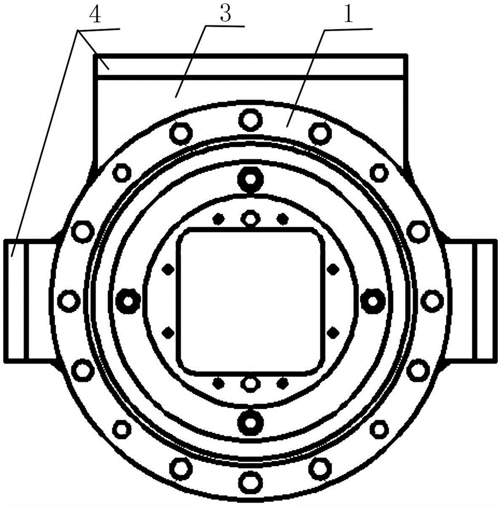
[0055] The multi-point excitation seismic test support frame includes a plurality of flanges 1 respectively arranged at the support points of the test piece and having the same structure as the actual installation structure at the support points of the test piece, a transition block 3 arranged on the flange 1, and The connecting plate 4 set on the flange 1 through the transition block 3, such as figure 2 shown.
[0056] In the present invention, because the flange 1 is located at the support point of the test piece, and the structure of the flange 1 is consistent with the actual installation structure at the support point of the test piece, that is, the installation method between the test piece and the flange 1 is the same as that of the test piece in the pile. The actual installation method is consistent, thus ensuring that the installation method of the control rod drive line on the present invention is consistent with the installation condition of the real stack.
[0057...
Embodiment 2
[0068] The difference between this embodiment and Embodiment 1 is that this embodiment optimizes the specific structure of the spring plate decoupling mechanism 5, such as Figure 4 As shown, the specific arrangement of the spring plate decoupling mechanism 5 is as follows:
[0069] The spring plate decoupling mechanism 5 includes a square upper flange 51, a square lower flange 52, a spring plate 53 connected to the upper flange 51 by bolts at one end and connected to the lower flange 52 by bolts at the other end, and a set Flexible pipe 54 between upper flange 51 and lower flange 52 .
[0070] In this embodiment, the number of spring plates 53 in the spring plate decoupling mechanism 5 is four, which are respectively arranged on opposite sides of the square upper flange 51 and the square lower flange 52, as Figure 4 shown.
[0071] In this embodiment, the upper flange 51 and the lower flange 52 are arranged to facilitate the connection with the rigid cylinder 2 and the fla...
Embodiment 3
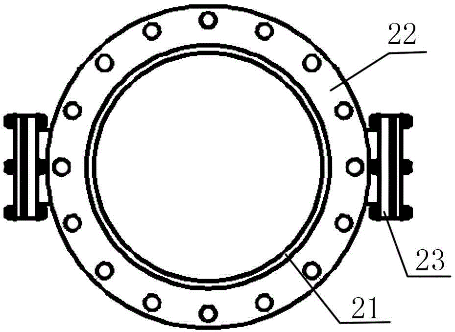
[0074] The difference between this embodiment and embodiment 1 or embodiment 2 is that this embodiment optimizes the specific structure of the rigid cylinder 2, such as image 3 As shown, the specific arrangement of the rigid cylinder 2 is as follows:
[0075] The rigid cylinder 2 includes a cylinder body 21 , circular flanges 22 arranged at both ends of the cylinder body 21 , and a hand hole connection 23 arranged on the cylinder body 21 .
[0076] Through the setting of the round flanges 22 at both ends, the connection between the rigid cylinder 2 and the flange 1 and the spring plate decoupling mechanism 5 is effectively facilitated, and the connection is more convenient; at the same time, the setting of the hand hole connection tube 23 effectively facilitates the connection of the relevant test leads. The tightening operation of bolted joints that lead out or are located inside and below.
PUM
 Abstract
Description
Claims
Application Information
 - R&D
- Intellectual Property
- Life Sciences
- Materials
- Tech Scout
- Unparalleled Data Quality
- Higher Quality Content
- 60% Fewer Hallucinations
Browse by: Latest US Patents, China's latest patents, Technical Efficacy Thesaurus, Application Domain, Technology Topic, Popular Technical Reports.
© 2025 PatSnap. All rights reserved.Legal|Privacy policy|Modern Slavery Act Transparency Statement|Sitemap|About US| Contact US: help@patsnap.com


