Multi-point excitation seismic test support frame and its design method

A technology of anti-seismic test and support frame, which is applied in the field of support frame, and can solve the problems that cannot be carried out under the condition of installation

Active Publication Date: 2017-11-03
NUCLEAR POWER INSTITUTE OF CHINA
View PDF5 Cites 0 Cited by
  • Summary
  • Abstract
  • Description
  • Claims
  • Application Information

AI Technical Summary

Problems solved by technology

[0005] At this stage, this type of test cannot be carried out under the actual installation state of the test piece. In order to simulate the support and installation of the entire set of drive lines or other similar types of slender structures under the actual installation state, it is necessary to design a set of special simulation support structures.

Method used


Image

  • Multi-point excitation seismic test support frame and its design method
  • Multi-point excitation seismic test support frame and its design method
  • Multi-point excitation seismic test support frame and its design method

Examples


Embodiment 1

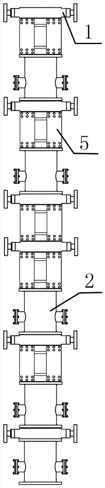
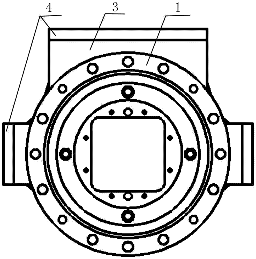
[0055] The multi-point excitation seismic test support frame includes a plurality of flanges 1 respectively arranged at the support points of the test piece and having the same structure as the actual installation structure at the support points of the test piece, a transition block 3 arranged on the flange 1, and The connecting plate 4 set on the flange 1 through the transition block 3, such as figure 2 shown.

[0056] In the present invention, because the flange 1 is located at the support point of the test piece, and the structure of the flange 1 is consistent with the actual installation structure at the support point of the test piece, that is, the installation method between the test piece and the flange 1 is the same as that of the test piece in the pile. The actual installation method is consistent, thus ensuring that the installation method of the control rod drive line on the present invention is consistent with the installation condition of the real stack.

[0057...

Embodiment 2

[0068] The difference between this embodiment and Embodiment 1 is that this embodiment optimizes the specific structure of the spring plate decoupling mechanism 5, such as Figure 4 As shown, the specific arrangement of the spring plate decoupling mechanism 5 is as follows:

[0069] The spring plate decoupling mechanism 5 includes a square upper flange 51, a square lower flange 52, a spring plate 53 connected to the upper flange 51 by bolts at one end and connected to the lower flange 52 by bolts at the other end, and a set Flexible pipe 54 between upper flange 51 and lower flange 52 .

[0070] In this embodiment, the number of spring plates 53 in the spring plate decoupling mechanism 5 is four, which are respectively arranged on opposite sides of the square upper flange 51 and the square lower flange 52, as Figure 4 shown.

[0071] In this embodiment, the upper flange 51 and the lower flange 52 are arranged to facilitate the connection with the rigid cylinder 2 and the fla...

Embodiment 3

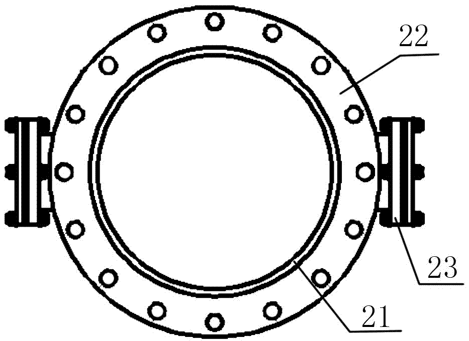
[0074] The difference between this embodiment and embodiment 1 or embodiment 2 is that this embodiment optimizes the specific structure of the rigid cylinder 2, such as image 3 As shown, the specific arrangement of the rigid cylinder 2 is as follows:

[0075] The rigid cylinder 2 includes a cylinder body 21 , circular flanges 22 arranged at both ends of the cylinder body 21 , and a hand hole connection 23 arranged on the cylinder body 21 .

[0076] Through the setting of the round flanges 22 at both ends, the connection between the rigid cylinder 2 and the flange 1 and the spring plate decoupling mechanism 5 is effectively facilitated, and the connection is more convenient; at the same time, the setting of the hand hole connection tube 23 effectively facilitates the connection of the relevant test leads. The tightening operation of bolted joints that lead out or are located inside and below.


PUM


Abstract

The invention discloses a support frame for a multi-point excitation anti-seismic test, which mainly solves the problem that such tests cannot be carried out under the actual installation state of the test piece at the present stage. The present invention includes a plurality of flanges (1) respectively arranged at the supporting points of the test pieces and having the same structure as the actual installation structure at the supporting points of the test pieces, a transition block (3) arranged on the flanges (1), and The connecting plate (4) is arranged on the flange (1) through the transition block (3). The invention has the advantages of effectively ensuring that the installation mode of the control rod drive line on the invention is consistent with the installation condition of the real pile.

Description

technical field [0001] The invention relates to a support frame, in particular to a multi-point excitation anti-seismic test support frame for reactor control rod drive lines or other similar elongated structures. Background technique [0002] In order to accurately simulate the seismic excitation of each component, the seismic test of the reactor control rod drive line or other similar slender structures is generally completed by the multi-point excitation experiment method. This type of test is usually carried out in a multi-point excitation shaft test device, and displacement control is often used in the control method, and the loading direction can be horizontal or horizontal or combined horizontal and vertical loading. [0003] According to HAF J0053 "Guidelines for Seismic Qualification Test of Nuclear Equipment", the installation method of the test piece in the seismic test should be consistent with the actual installation conditions, and the input load and loading me...

Claims


Application Information

Patent Timeline
Patent Type & Authority Patents(China)
IPC IPC(8): G01M7/02G01M7/06
CPCG01M7/02G01M7/06
Inventor 黄文慧李天勇马建中李锡华闫晓李朋洲杜建勇
Owner NUCLEAR POWER INSTITUTE OF CHINA
Why Eureka
Try Eureka