A Bidirectional Constant Current Source Device Based on Double Negative Feedback Control

A negative feedback, constant current source technology, applied in the field of electronics, can solve the problems of drop, increase, use limitation and so on

Inactive Publication Date: 2016-12-07
JILIN UNIV
View PDF5 Cites 0 Cited by
  • Summary
  • Abstract
  • Description
  • Claims
  • Application Information

AI Technical Summary

Problems solved by technology

Among these schemes, the first scheme is greatly affected by the device itself and has limited improvement in stability; the second scheme can effectively reduce the impact of changes in load resistance due to a large resistor connected in series in the load circuit. The influence of the output current, but due to the existence of the large resistance of the load circuit, the output current is very small, generally only in the milliampere level, and most of the power is dropped on the large resistance, which also makes the efficiency extremely low; the third scheme Due to the automatic adjustment function of the negative feedback network itself, the output current can be automatically stabilized without being affected by load changes, so it is currently the most effective way to improve current stability. However, in the currently disclosed technologies, generally Adopting a single linear feedback network, the biggest disadvantage of this scheme is that once the feedback network fails, the system will be in an open-loop working state, the output current will increase sharply, and it is easy to damage the load and the circuit itself. Another disadvantage is the use of The occasion is limited, and it can only be applied to the occasion where the load responds linearly to the current. In some specific occasions, if the load responds to the current with a delay or lead, this constant current source based on a single linear feedback network will lose automatic stabilization capability
In addition, most of the current common constant current sources are unidirectional output. When bidirectional current is required in some occasions (such as heating or cooling of temperature control devices), its use will be limited.

Method used


Image

  • A Bidirectional Constant Current Source Device Based on Double Negative Feedback Control
  • A Bidirectional Constant Current Source Device Based on Double Negative Feedback Control
  • A Bidirectional Constant Current Source Device Based on Double Negative Feedback Control

Examples


Embodiment 1

[0038] Embodiment 1 Overall structure of the present invention

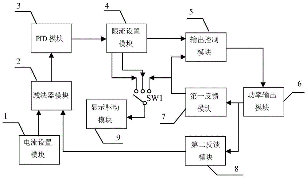
[0039] combine figure 2 The overall working principle of a bidirectional constant current source circuit of the present invention is described. A reference voltage is set through the current setting module 1, and the second feedback module 8 samples the output current and converts it into a corresponding voltage. The above two voltages are differenced in the subtractor module 2, and the difference is sent to the PID module 3 for PID Operation, the result of the operation is sent to the current limiting setting module 4, and the output value of the current limiting setting module 4 is sent to the control input terminal of the output control module 5 as a control voltage, compared with the feedback voltage of the first feedback module 7, and the output value is controlled The power output module 6 outputs current. Since the whole system is in a double negative feedback working state, the output current will chang...

Embodiment 2

[0040] Embodiment 2 The current setting module 1 of the present invention

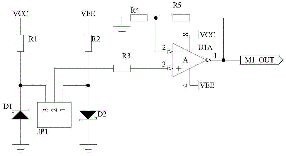
[0041] The principle circuit of the current setting module 1 of the present invention is as image 3As shown, one end of the resistor R1 is connected to the power supply VCC, the other end is connected to the cathode of the Zener diode D1 and pin 3 of the 3-core interface JP1, the anode of the Zener diode D1 is grounded, one end of the resistor R2 is connected to the power supply VEE, and the other end is connected to the regulator The anode of diode D2 and pin 1 of 3-core interface JP1, the cathode of Zener diode D2 are grounded, the 2 pin of 3-core interface JP1 is connected to one end of resistor R3, and the other end of resistor R3 is connected to the non-inverting input terminal of op amp U1A, op amp The inverting input terminal of U1A is connected to one end of resistor R4 and one end of resistor R5, the other end of resistor R4 is grounded, the other end of resistor R5 is connected to the output...

Embodiment 3

[0043] Embodiment 3 Subtractor module 2

[0044] The principle circuit of subtractor module 2 of the present invention is as Figure 4 As shown, one end of the resistor R6 is used as an input end of the subtractor module 2, which is recorded as the port M2_IN2, and the inverting input terminal of the operational amplifier U1B is connected to the other end of the resistor R6 and one end of the resistor R9, and the other end of the resistor R9 is connected to the operational amplifier. The output terminal of U1B, one end of the resistor R7 is used as the other input terminal of the subtractor module 2, denoted as port M2_IN1, the non-inverting input terminal of the operational amplifier U1B is connected to the other end of the resistor R7 and one end of the resistor R8, and the other end of the resistor R8 is grounded , the output terminal of the operational amplifier U1B is used as the output terminal of the subtractor module 2, which is recorded as the port M2_OUT, and connect...


PUM


Abstract

The invention relates to a bi-directional constant current source device based on dual negative feedback control, and belongs to the technical field of electronic technique. The bi-directional constant current source device structurally comprises a front panel (10), a current setting module (1), an output control module (5), a power output module (6) and a first feedback module (7), and is characterized by further structurally comprising a subtracter module (2), a PID module (3), a limited current setting module (4), a second feedback module (8) and a display driver module (9). The bi-directional constant current source device adopts the dual negative feedback structure, thereby having the characteristics of being high in output current stability, high in safety, wide in range of usage occasions and the like, the limited current setting function is achieved, and output current dual-directional regulation can be further realized.

Description

technical field [0001] The present invention belongs to the technical field of electronic technology. In particular, it relates to a high stability bidirectional constant current source device based on double negative feedback control. Background technique [0002] The constant current source has important applications in many occasions such as optical fiber communication, LED lighting, and laser drive. In some occasions, such as laser drive, the output current stability of the constant current source is very important, and the instability of the output current will cause Affect the life of the laser and the output optical power. Commonly used measures to improve current stability are: 1. Using the nonlinear magnetization principle of magnetic saturation reactor to improve stability; 2. Connecting a large resistance in series in the load circuit (relative to the load resistance); 3. Realizing the current through the negative feedback network Automatic stabilization. Among...

Claims


Application Information

Patent Timeline
Patent Type & Authority Patents(China)
IPC IPC(8): G05F1/46H02M3/155
CPCG05F1/461H02M3/155
Inventor 汝玉星高博吴戈单江东田小建刘大恺张大朋安明梁雪李尚马春阳
Owner JILIN UNIV
Why Eureka
Try Eureka