Eureka AIR delivers breakthrough ideas for toughest innovation challenges, trusted by R&D personnel around the world.

High Dynamic Stability Switching Appliances

A technology for switching electrical appliances and stability, which is applied in the field of switching electrical appliances with high dynamic stability. It can solve problems such as unfavorable contact breaking, limiting breaking capacity, and increasing power consumption of the operating system, so as to improve short-term tolerance and reduce system power. consumption, improve the effect of short-term withstand capacity and on-off capacity

Active Publication Date: 2017-07-25
SCHNEIDER WINGOAL TIANJIN ELECTRIC EQUIP
View PDF4 Cites 0 Cited by
  • Summary
  • Abstract
  • Description
  • Claims
  • Application Information

AI Technical Summary

Problems solved by technology

Improving the dynamic stability of switching devices needs to increase the short-time withstand current and the switching current at the same time, which is contradictory to a certain extent. To improve the short-term withstand current needs to increase the contact pressure, and the contact pressure is too high. Pressure, on the one hand, increases the power consumption of the operating system, on the other hand, because it offsets the electric repulsion, it is not conducive to the breaking of the contacts, thus limiting the breaking capacity
Existing switching devices cannot well solve the balance problem between the two

Method used


Image

  • High Dynamic Stability Switching Appliances
  • High Dynamic Stability Switching Appliances
  • High Dynamic Stability Switching Appliances

Examples


Embodiment Construction

[0028] The structure of the high dynamic stability switching device provided by the present invention will be described in detail below in conjunction with the embodiments.

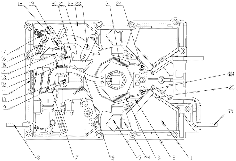
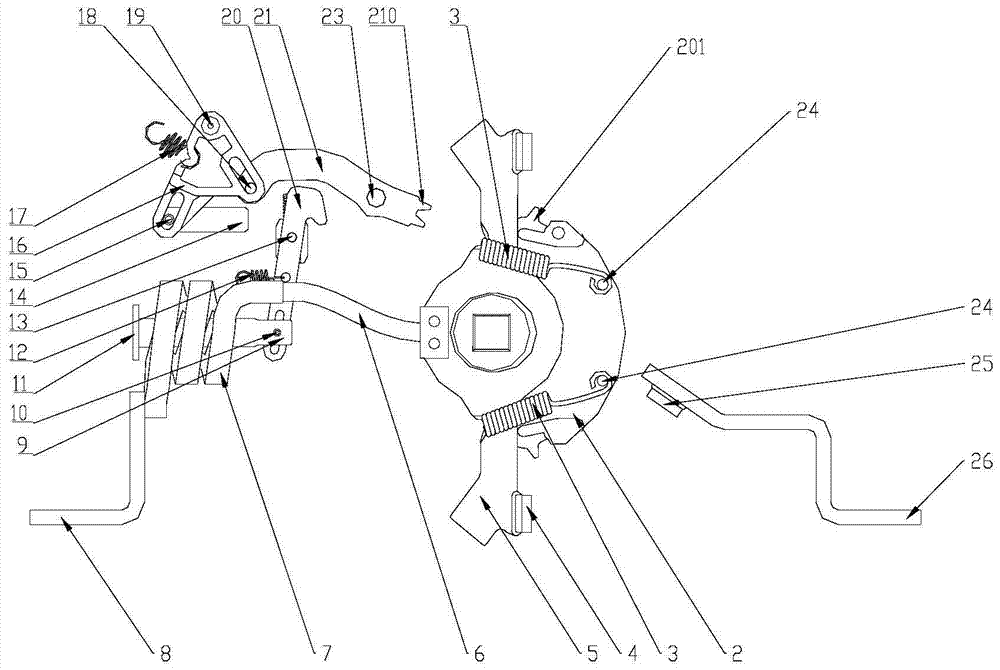
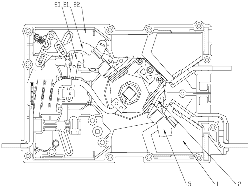
[0029] Such as figure 1 , 1a As shown, a switching device with high dynamic stability is installed on the square main shaft of the mechanism, including a housing 22, an electromagnetic force generating part, a linkage part, a moving contact part and a static contact part;

[0030] The static contact part is fixed on the housing 22, including a static contact body 26 and a static silver point 25 arranged at its front end;

[0031] The moving contact part includes a moving contact body 5, a moving silver point 4 and a moving contact housing 2; the middle part of the moving contact body 5 is ring-shaped, and the two sides extend outward to form contacts respectively; one of the contacts The side of the moving silver point 4 is provided with the moving silver point 4. When the moving contact body 5 rotates,...


PUM


Abstract

The invention discloses a high-dynamic-stability switching device which is mounted on a square main shaft of a mechanism. The high-dynamic-stability switching device comprises the components of a housing, an electromagnetic force generating component, linkage components, a dynamic contact component a static contact component. The dynamic contact component comprises a dynamic contact body, dynamic silver contacts which are arranged at ends of the dynamic contact body, and a dynamic contact housing. The dynamic contact housing matches the dynamic contact body, and furthermore the dynamic contact housing and the dynamic contact body are fixed through springs. The dynamic contact housing is provided with teeth. The electromagnetic force generating component comprises the components of a load terminal, an electromagnetic coil, a flexible connecting line, a dynamic iron core and a static iron core; wherein the load terminal, the electromagnetic coil, the flexible connecting line, the dynamic iron core and the static iron core are connected. The flexible connecting line is connected with the dynamic contact. The linkage components comprise a hook plate, an insertion plate, a spin orbit and a swing plate. After teeth on the dynamic contact housing engage with the swing plate, the swing plate is driven to rotate. The swing plate drives the spin orbit, and the spin orbit drives the insertion plate. The dynamic contact body rotates and drives the hook plate. The hook plate drives the dynamic iron core to move. The high-dynamic-stability switching device utilizes the electromagnetic force for compensating a contact pressure and has high dynamic stability.

Description

technical field [0001] The invention belongs to the technical field of power switches, in particular to a high dynamic stability switching device. Background technique [0002] Switching appliances such as isolating switching appliances and PC-level transfer switching appliances need to meet the requirements of short-term withstand capability and on-off capability at the same time, and at the same time, it is necessary to minimize the power consumption of the operating system. The dynamic stability of the switching device mainly depends on the short-term withstand capacity and the breaking capacity of the switching device. Improving the dynamic stability of switching devices needs to increase the short-time withstand current and the switching current at the same time, which is contradictory to a certain extent. To improve the short-term withstand current needs to increase the contact pressure, and the contact pressure is too high. Pressure, on the one hand, increases the po...

Claims


Application Information

Patent Timeline
Patent Type & Authority Patents(China)
IPC IPC(8): H01H1/54H01H9/20
CPCH01H1/54H01H9/20
Inventor 陈红群张军周慧谢勇郭小龙吕敏强王佳砚
Owner SCHNEIDER WINGOAL TIANJIN ELECTRIC EQUIP
Why Eureka
Eureka Blog
Learn More