

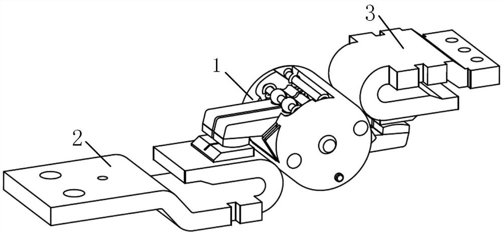
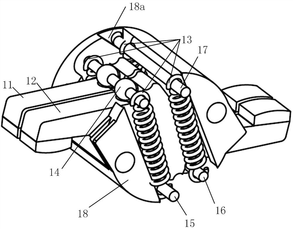
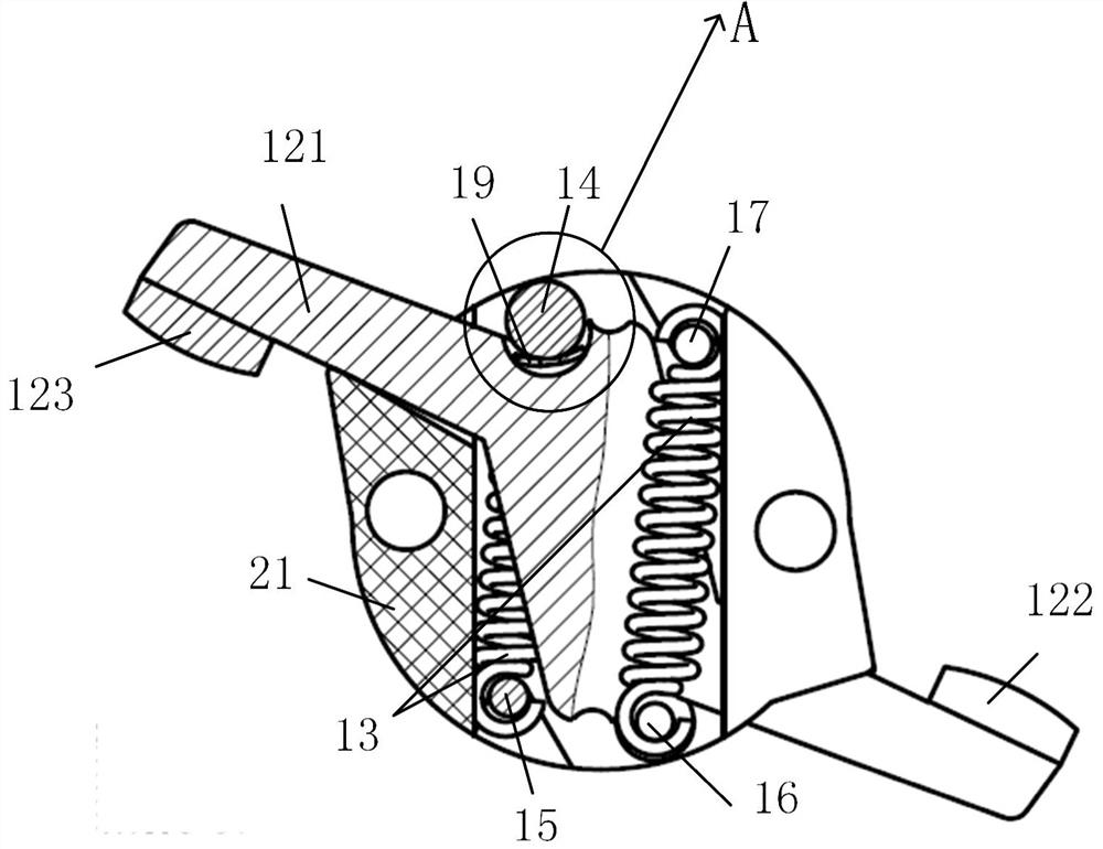
A rotary multi-finger contact structure
A rotary, contact finger technology, applied in the direction of contact, contact engagement, circuit breaker contact, etc., can solve the problem of temperature rise that is difficult to solve, difficult to achieve the expected effect, and arc re-ignition, etc., to increase the effective contact area, improving short-term tolerance, and reducing the effect of electrodynamic repulsion
- Summary
- Abstract
- Description
- Claims
- Application Information
AI Technical Summary
Problems solved by technology
Method used
Image

Examples
Embodiment Construction
[0024] The present invention will be described in further detail below in conjunction with the accompanying drawings.
[0025] The purpose of the present invention is to overcome the existing rotary contact structure: (1) too high temperature rise; (2) low short-term tolerance; (3) poor simultaneity; (4) high manufacturing and assembly requirements; ( 4) It is easy to drop and cause welding problems. A new type of rotating multi-finger contact structure is provided. The contact structure automatically adjusts the center position through the line contact between the ball and the ring without excessive manufacturing accuracy. The consistency of contact pressure between different contact fingers and the simultaneity of two fractures of the same contact finger can be guaranteed. It is also designed with an anti-drop structure, which can maintain the open state of the contacts after the contacts are opened at a certain angle, which can prevent the contacts from falling after openin...
PUM
 Abstract
Description
Claims
Application Information