Eureka AIR delivers breakthrough ideas for toughest innovation challenges, trusted by R&D personnel around the world.

Moving contact system of circuit breaker

A technology for moving contacts and circuit breakers, which is applied to circuit breaker contacts, circuit breaker components, etc., can solve the problems of poor installation consistency of the splints on both sides, attenuation of spring force values, and influence on the consistency of overtravel of products. Improve short-term tolerance, reduce force decay, and improve consistency

Pending Publication Date: 2022-06-21
SHANGHAI LIANGXIN ELECTRICAL
View PDF0 Cites 0 Cited by
  • Summary
  • Abstract
  • Description
  • Claims
  • Application Information

AI Technical Summary

Problems solved by technology

[0004] The installation position of the contact spring of a traditional circuit breaker is located behind the moving silver point. When the product passes a short-circuit current, because the contact spring is close to the heating point, the spring force value is attenuated due to heat, which affects the short-term withstand capacity of the product; when the product is broken The generated particles are easy to enter the contact spring, which can easily cause the spring to be unable to compress and the product to fail to close
[0005] The moving contact piece of the traditional circuit breaker uses two splints to fasten the contact support with self-tapping screws through the moving contact shaft. The installation consistency of the splints on both sides is poor, which will easily lead to the deflection of the moving contact and affect the consistency of the overtravel of the product. At the same time, the self-tapping screw connection installation method has the risk of falling out, and the self-tapping screw and the housing will interfere with the separation of the product Closing reliability

Method used


Image

  • Moving contact system of circuit breaker
  • Moving contact system of circuit breaker
  • Moving contact system of circuit breaker

Examples


Embodiment Construction

[0030] The technical solutions of the present invention will be clearly and completely described below with reference to the accompanying drawings. Obviously, the described embodiments are part of the embodiments of the present invention, but not all of the embodiments. Based on the embodiments of the present invention, all other embodiments obtained by those of ordinary skill in the art without creative efforts shall fall within the protection scope of the present invention.

[0031] In the description of the present invention, it should be noted that the orientation or positional relationship indicated by the terms "inside", "outside", etc. is based on the orientation or positional relationship shown in the accompanying drawings, and is only for the convenience of describing the present invention and simplifying the description, It is not intended to indicate or imply that the device or element referred to must have a particular orientation, be constructed and operate in a pa...


PUM


Abstract

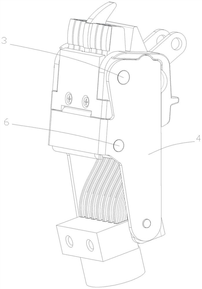
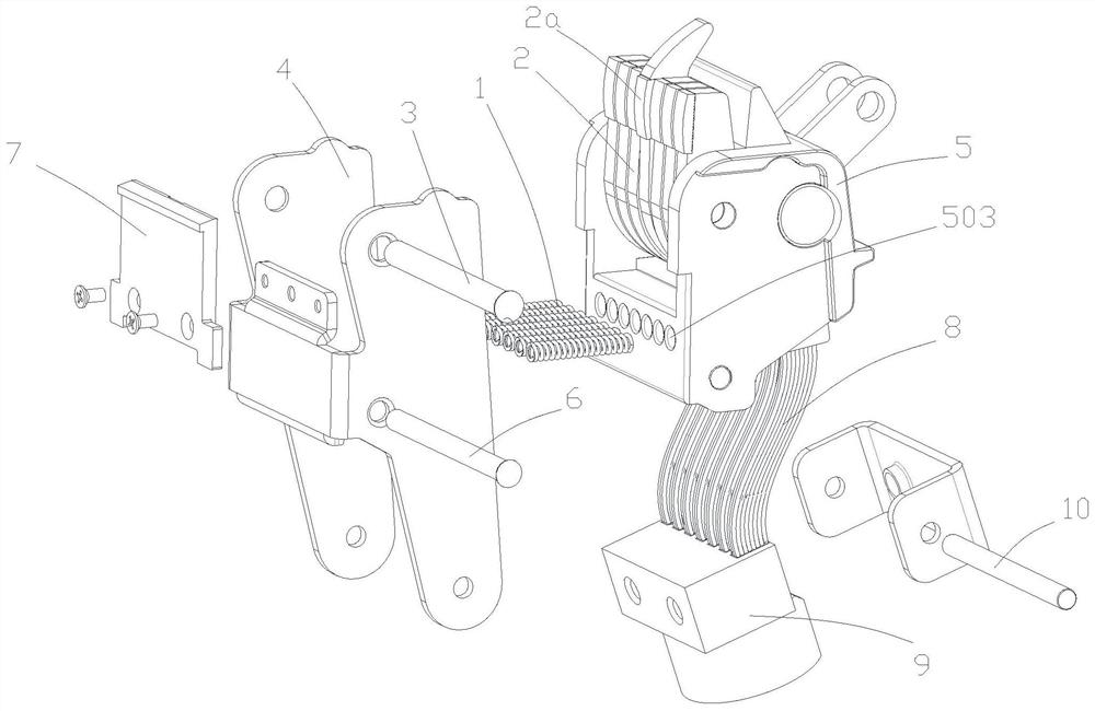
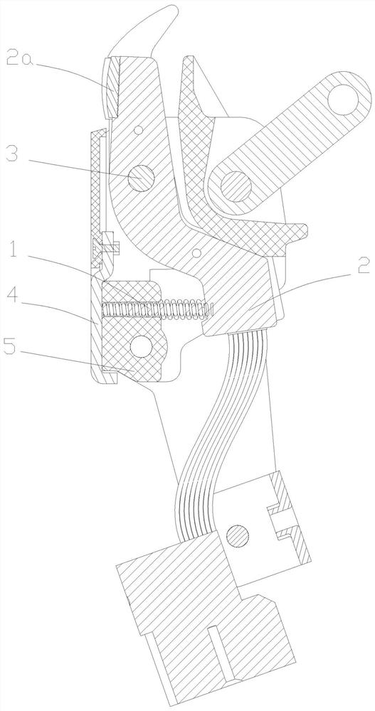
A moving contact system of a circuit breaker is characterized in that one end of a contact spring (1) abuts against a moving contact piece set (2) and is located at the position, on one side of a moving silver point (2a), of the moving contact piece set (2), the contact spring (1) is located below the moving silver point (2a), and the contact spring (1) is located at the position, on the other side of a moving contact piece rotating shaft (3), relative to the moving silver point (2a). According to the utility model, the force value attenuation of the contact spring can be effectively avoided, the short-time endurance capability of the product is improved, particles generated during the breaking of the product are difficult to enter the contact spring, the smooth closing of the product is facilitated, the installation consistency of the moving contact is improved, and the closing reliability of the moving contact is improved.

Description

technical field [0001] The invention belongs to the technical field of low-voltage electrical appliances, and in particular relates to a moving contact system of a circuit breaker. Background technique [0002] Circuit breakers are an important part of power distribution appliances and are mainly used in industrial low-voltage power systems to connect and break currents in power grid circuits and to protect lines and power equipment from overload, undervoltage, short circuit, single-phase grounding and other faults. hazard. [0003] Circuit breakers are divided into high voltage circuit breakers and low voltage circuit breakers according to their scope of use. Low-voltage circuit breaker, also known as automatic switch, commonly known as "air switch" also refers to low-voltage circuit breaker. It is an electrical appliance that has both manual switching functions and automatic voltage loss, undervoltage, overload, and short circuit protection. It can be used to distribute ...

Claims


Application Information

Patent Timeline
IPC IPC(8): H01H73/04
CPCH01H73/04
Inventor 陆赛玉何春聂玉言孔惟丰崔华
Owner SHANGHAI LIANGXIN ELECTRICAL
Why Eureka
Eureka Blog
Learn More