A collector head and a current receiver equipped with the collector head

A technology of current collectors and current collectors, applied in the field of current collectors, can solve problems such as being unable to withstand short-term high current, and achieve the effects of improving short-term tolerance, increasing contact pressure, and increasing contact area

Active Publication Date: 2022-05-13
ZHUZHOU ELECTRIC LOCOMOTIVE CO LTD
View PDF0 Cites 0 Cited by
  • Summary
  • Abstract
  • Description
  • Claims
  • Application Information

AI Technical Summary

Problems solved by technology

[0005] In order to solve the problem that the collector head of the current receiver in the background technology cannot withstand short-term high current, the present invention provides a collector head, the specific technical solution is as follows

Method used


Image

  • A collector head and a current receiver equipped with the collector head
  • A collector head and a current receiver equipped with the collector head
  • A collector head and a current receiver equipped with the collector head

Examples


Embodiment 1

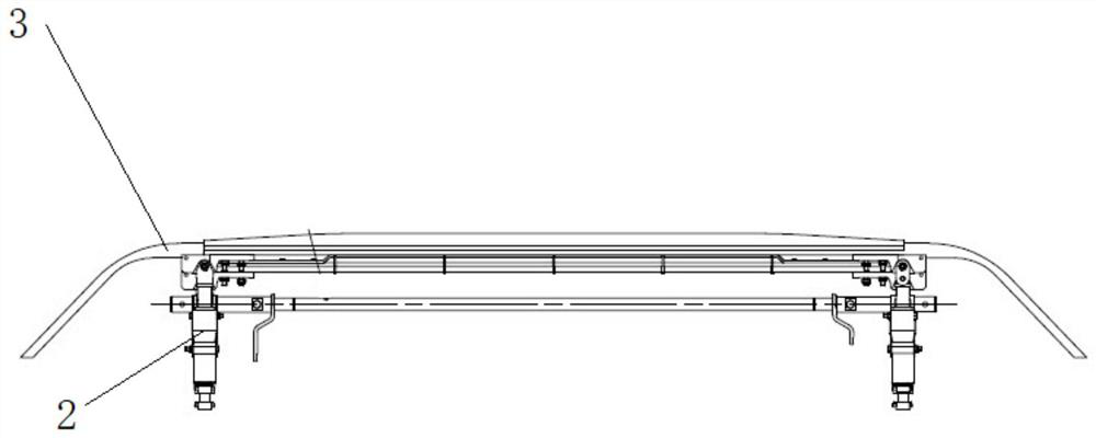
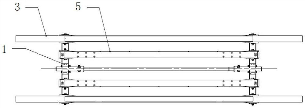
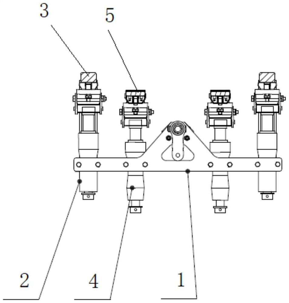
[0029] Such as Figure 1-Figure 3 As shown, a current collector includes a mounting bracket 1, two first slide assemblies 3 mounted on the mounting bracket 1 through two first compression springs 2, and two second compression springs 4 mounted on the Two second slider assemblies 5 on the mounting bracket 1, the second slider assemblies 5 are parallel to the first slider assembly 3, and the second slider assemblies 5 are located inside the first slider assembly 3 . Specifically, the lower ends of the two first compression springs 4 are respectively connected to the two ends of the mounting bracket 1, and the top ends are respectively connected to the two ends of the first slide assembly 3; the lower ends of the two second compression springs 4 They are respectively connected to the two ends of the mounting bracket 1 , and the top ends are respectively connected to the two ends of the second slide assembly 5 . The first slide assembly 3 is higher than the second slide assembly...

Embodiment 2

[0034] Such as Figure 8 As shown, a current collector is equipped with the current collecting head 6 described in Embodiment 1, and is also provided with an air bag lifting device 7 for lifting the collecting head, and the air bag lifting bow The device 7 is provided with two airbags 71 . The airbag bow-raising device in the current collector is usually equipped with only one airbag. In this embodiment, by adding an airbag 71, the bow-raising moment can be effectively increased, and the contact pressure between the collector head 6 and the catenary can be increased, further Improve short-term tolerance.


PUM


Abstract

A current collector, comprising a mounting bracket and a first slide assembly mounted on the mounting bracket, and also including a second slide assembly mounted on the mounting bracket, the second slide assembly is connected to the first slide assembly The components are parallel, and the side of the second skateboard component used to contact the catenary is provided with a braided wire layer, the braided wire layer is a conductor, and the braided wire layer is connected to the first skateboard component and the second skateboard respectively. The components are electrically connected. Due to the adoption of the above technical solution, compared with the prior art, the present invention can increase the contact area between the current collector and the catenary by increasing the second slide assembly with the conductor braided wire layer on the upper surface, and improve the current-carrying capacity, thereby Make the collector head able to withstand short-term high current. On the other hand, by designing the height of the first slide assembly to be higher than that of the second slide assembly, it is possible to prevent the catenary from burning the conductor braided wire layer on the second slide set.

Description

technical field [0001] The invention relates to the field of rail transit equipment, in particular to a collector head and a current collector equipped with the collector head. Background technique [0002] There are two main ways for rail vehicles such as main line electric locomotives, urban rail vehicles, EMUs, engineering maintenance vehicles, and new energy storage vehicles to take current from the power supply system. One is to use the roof pantograph to contact the catenary to receive current ; The other is to use the receiver or charging device to make static contact with the charging rail of the ground charging station to receive current; The quality of performance directly determines the quality and reliability of the pantograph / receiver. [0003] The pantograph and catenary transmission current is small, and the pantograph bow head generally adopts two sets of pure carbon-carbon slides or two sets of metal-impregnated carbon slides or a single metal-impregnated c...

Claims


Application Information

Patent Timeline
Patent Type & Authority Patents(China)
IPC IPC(8): B60L5/20B60L5/32
CPCB60L5/20B60L5/32B60L2200/26
Inventor 蒋聪健吕阶军张艳芳梁坤李军冯叶王秋红
Owner ZHUZHOU ELECTRIC LOCOMOTIVE CO LTD
Why Eureka
Try Eureka