
A molded case circuit breaker multi-touch finger moving contact and contact system

A moulded case circuit breaker and moving contact technology, applied in circuit breaker contacts, circuit breaker parts, overload protection circuit breakers, etc., can solve the problem of large contact spring design, difficult contact spring design, and contact resistance. It can increase the effective contact area, improve the short-term tolerance, and reduce the contact resistance.

Active Publication Date: 2022-07-05
WUHAN MARINE ELECTRIC PROPULSION RES INST CHINA SHIPBUILDING IND CORP NO 712 INST
View PDF22 Cites 0 Cited by
  • Summary
  • Abstract
  • Description
  • Claims
  • Application Information

AI Technical Summary

Problems solved by technology

[0004] During the development of the double-breakpoint conductive system, a series of problems have also been exposed, mainly the problem of the moving contact. Difficult to solve; high contact resistance and severe contact heating bring about another problem: the temperature of the moving contact is too high, which accelerates the aging of the moving contact frame of the insulating part, and at the same time causes annealing of the contact spring, contact pressure, The reduction of contact pressure and overtravel will cause the contact resistance of each moving and static contact position to increase, and the heating will become more and more serious, vicious circle until the entire conductive system fails
[0005] The contact springs of the rotary double-break point moving contact structure currently used in the market are all extension springs, and the form of symmetrical double extension springs makes the force arm of the contact spring against the moving contact rod very small, ensuring the contact pressure. Under the circumstances, the tension of the contact spring is very large. Due to the limitation of the space of the moving contact, the stiffness of the contact spring is usually designed to be very large, the design of the contact spring is difficult, and the reliability is relatively low. Not only that, too large a contact spring The force makes the place where the contact spring is installed on the moving contact frame have a large pressure and is prone to cracking; in the usual rotary double-break point moving contact assembly, the moving contact rod is directly installed on the moving contact through symmetrical double tension springs. On the frame, it can move back and forth, there is no rotating shaft, and the pulling force of the two tension springs needs to be the same to ensure that the moving contact rod is in the center of the moving contact frame. However, due to the high stiffness of the tension spring, small processing errors and assembly errors All will cause the moving contact rod to deviate from the center position, resulting in the simultaneity of the two fractures of the same moving contact when closing and opening; the rotary double breakpoint structure doubles the electric repulsion compared with the ordinary single breakpoint structure, Easier to repel, although the current limiting effect is good, but the short-term tolerance is low, in the environment that requires selective protection, it is difficult to achieve the expected effect due to too early repelling

Method used


Image

  • A molded case circuit breaker multi-touch finger moving contact and contact system
  • A molded case circuit breaker multi-touch finger moving contact and contact system
  • A molded case circuit breaker multi-touch finger moving contact and contact system

Examples


Embodiment Construction

[0030] The present invention will be further described in detail below in conjunction with the accompanying drawings.

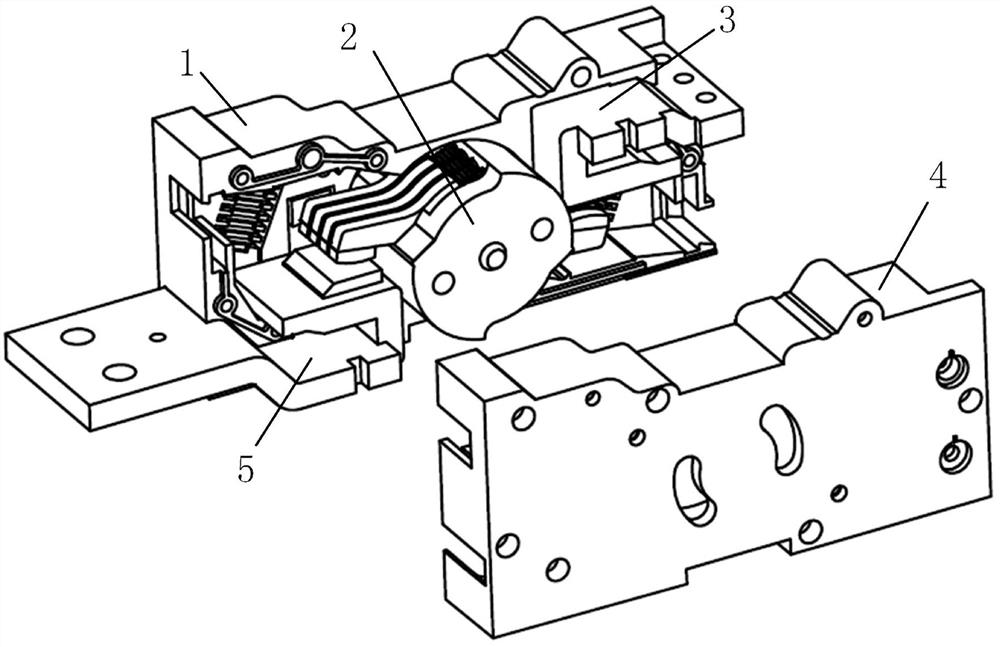
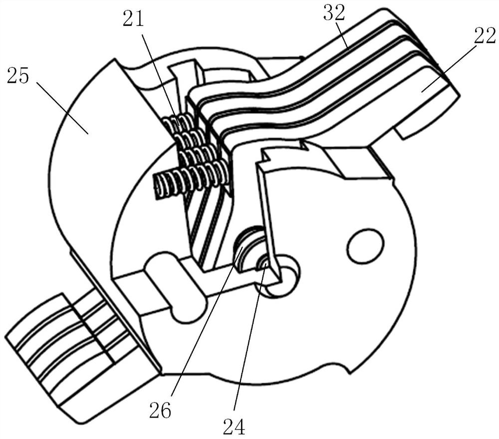
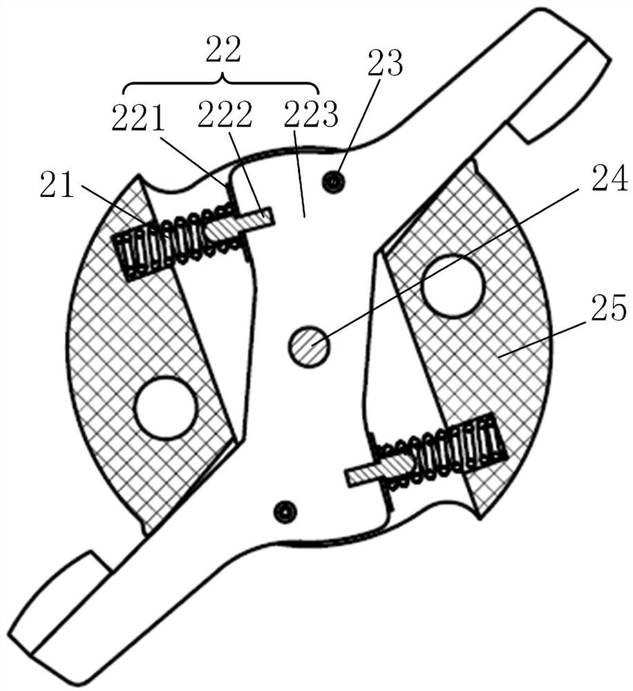
[0031] The purpose of the present invention is to overcome the existing rotary contact structure: (1) the temperature rise is too high; (2) the short-term tolerance is low; (3) the same contact finger is difficult to be centered and installed consistently, and double-break contact The simultaneity is poor; (4) The manufacturing and assembly requirements are high; (4) The contact spring force value is too large, and the contact bracket is easy to collapse. The provided multi-finger moving contact of the molded case circuit breaker adopts symmetrical double compression springs. Provide contact pressure, improve the contact spring force arm, can greatly reduce the spring force of each contact spring while ensuring the contact pressure Cracked head bracket insulation. The contact rod is installed on the contact bracket through the rotating shaft, which ensures t...


PUM


Abstract

The invention discloses a multi-finger moving contact of a molded case circuit breaker. The moving contact can be fixedly installed with an upper static contact, a lower static contact, a left casing and a right casing to form a contact system; the moving contact consists of Contact holder, contact finger, spacer, spacer, contact spring, shaft, right bearing, left bearing, right bearing stop spring, right contact finger stop spring, left bearing stop spring and left contact finger The rotating shaft is installed on the contact frame through the left bearing and the right bearing, and multiple contact fingers are installed on the rotating shaft in parallel. Each contact finger can rotate around the rotating shaft independently without interfering with each other. The partition plate and the spacer are installed Between each two contact fingers, the gap between the contact fingers is ensured, and two contact springs are symmetrically installed on each contact finger to provide contact pressure, which increases the force arm of the contact spring to provide thrust , thereby reducing the force value of the contact spring itself and the stress on the contact bracket where the contact spring is installed, greatly improving the reliability of the moving contact.

Description

technical field [0001] The invention relates to the field of low-voltage electrical appliances, in particular to a multi-finger moving contact of a molded case circuit breaker, and a contact system based on the contact structure. Background technique [0002] Molded case circuit breaker is a power distribution appliance used in the power grid, which can connect, carry and break current under normal circuit conditions, and can also be used under specified abnormal conditions (such as overload, short circuit, undervoltage, and single-phase occurrences). Ground fault) plastic shell switchgear that makes, carries a certain time and breaks current. [0003] Molded case circuit breakers can be divided into three parts: conduction system, protection system and operating mechanism according to the structure. The conduction system plays the role of conducting current and is one of the core components of the circuit breaker. The double-breakpoint conduction system distributes the sho...

Claims


Application Information

Patent Timeline
Patent Type & Authority Patents(China)
IPC IPC(8): H01H73/04H01H1/20H01H1/22H01H1/10
CPCH01H73/045H01H1/2041H01H1/221H01H1/10
Inventor 祝聪章程罗欣宇徐庭伟沈文
Owner WUHAN MARINE ELECTRIC PROPULSION RES INST CHINA SHIPBUILDING IND CORP NO 712 INST
Learn More