Clamping device and wiring box using the same

A technology of clamping device and splint, which is applied in the direction of elastic/clamping device, circuit arrangement on the support structure, electrical components, etc., can solve the problems that cannot be put in, the wiring equipment cannot be placed stably, and is easy to shake, etc., to achieve extended use range effect

Inactive Publication Date: 2013-05-22
HUIZHOU KELIN ELECTRICAL APPLIANCE
View PDF2 Cites 8 Cited by
  • Summary
  • Abstract
  • Description
  • Claims
  • Application Information

AI Technical Summary

Problems solved by technology

However, the isolated space is fixed, and the size and specifications of different manufacturers or different types of wiring equipment are different. When the wiring equipment is

Method used


Image

  • Clamping device and wiring box using the same
  • Clamping device and wiring box using the same
  • Clamping device and wiring box using the same

Examples


Embodiment Construction

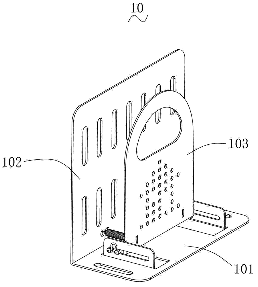
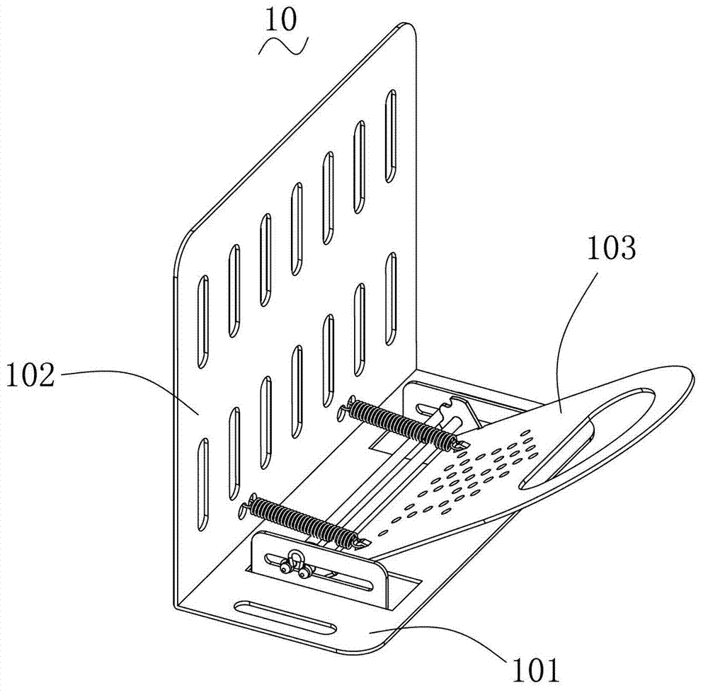
[0030] Such as figure 1 with figure 2 As shown, it is a three-dimensional structure diagram of the clamping device 10 in two different states according to an embodiment of the invention.

[0031] The clamping device 10 includes a base plate 101 , a back plate 102 and a clamping plate 103 , the base plate 101 and the back plate 102 are vertically connected, and the clamping plate 103 is rotatably mounted on the base plate 101 .

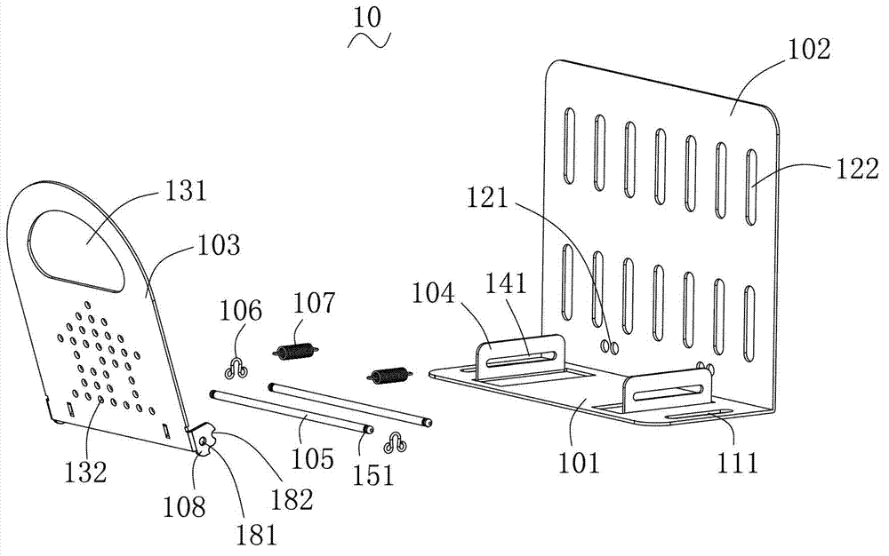
[0032] Please also see image 3 with Figure 4 , which is figure 2 The shown schematic diagrams of the exploded structure of the clamping device 10 from two different viewing angles.

[0033] The clamping device 10 also includes: two baffles 104 , two sliding rods 105 , an elastic member 106 , a spring 107 and a positioning part 108 .

[0034] Two baffles 104 are fixed on the bottom plate 101 in parallel and perpendicular to the back plate 102 . Both baffles 104 are provided with strip-shaped guide grooves 141 perpendicular to the backplane 101...


PUM


Abstract

A clamping device comprises a bottom plate, a back plate, a clamping plate, two baffles, two sliding rods, a spring and a positioning portion. The two baffles are fixed on the bottom plate in a parallel mode and are both provided with strip-shaped guide grooves, two ends of each sliding rod respectively penetrate through the guide grooves in the corresponding baffle, the positioning portion is connected with a position on the clamping plate close to a side edge and is provided with a through hole and two clamping grooves, the sliding rod far from the back plate penetrates through the through hole in the positioning portion, the two clamping grooves are clamped onto the sliding rod close to the back plate in a switchable mode, and two ends of the spring are respectively connected with a position of the back plate close to the bottom plate and a position of the clamping plate close to the bottom plate. The invention further provides a wiring box. Articles are opened and clamped through the clamping device in the mode that the clamping plate is turned over, an arm of force is large, operation is easy, and especially under the condition that a space is small, the turning-over-type clamping plate can be conveniently used for placement of the clamped articles. Meanwhile, due to the fact that the sliding rods can slide in the guide grooves, the clamping device can tightly clamp the articles with different thicknesses.

Description

technical field [0001] The invention relates to a clamping device, in particular to a clamping device with elastic force and a wiring box using the clamping device. Background technique [0002] Nowadays, whether it is inside the home or in the office building, there are a large number of electrical equipment, such as the Internet, TV and so on. All these electrical devices need to be wired in from the outside. [0003] The current decoration is basically to set all kinds of lines (network cable, cable TV line, etc.) in the wall and manage them in a unified way, so products such as wiring boxes appear. Its function is that the joints of various electrical appliances are uniformly arranged in the wiring box, and all kinds of lines introduced from the outside and through the wall are unified in the wiring box. This facilitates subsequent connection and maintenance. The wiring box can also be placed and used directly without being installed in the wall. [0004] After all k...

Claims


Application Information

Patent Timeline
IPC IPC(8): H05K7/12H02G3/08
Inventor 郭玉忠李贵平
Owner HUIZHOU KELIN ELECTRICAL APPLIANCE
Why Eureka
Try Eureka