AI technical title is built by PatSnap AI team. It summarizes the technical point description of the patent document.
A cutting machine and pipe technology, which is applied to pipe cutting devices, shearing devices, metal processing machinery parts, etc., can solve the problems of low cutting efficiency of pipe cutting machines, and achieve the effect of improving cutting efficiency, facilitating rotation and prolonging service life.
Active Publication Date: 2017-07-25
佛山市三三得钢业有限公司
View PDF9 Cites 11 Cited by
Summary
Abstract
Description
Claims
Application Information
AI Technical Summary
This helps you quickly interpret patents by identifying the three key elements:
Problems solved by technology
Method used
Benefits of technology
Problems solved by technology
[0003] The purpose of the present invention is to provide a high-efficiency pipe cutting machine, which has the advantage of high cutting efficiency and solves the problem of low cutting efficiency of the pipe cutting machine
Method used
Image
Click on the blue label to locate the original text in one second.
Reading with bidirectional positioning of images and text.
Examples
Embodiment Construction
[0020] (In the description of the present invention, it is to be understood that the terms "center", "longitudinal", "transverse", "length", "width", "thickness", "upper", "lower", "front", Orientation indicated by "back", "left", "right", "vertical", "horizontal", "top", "bottom", "inner", "outer", "clockwise", "counterclockwise", etc. Or the positional relationship is based on the orientation or positional relationship shown in the drawings, which is only for the convenience of describing the present invention and simplifying the description, and does not indicate or imply that the referred equipment or elements must have a specific orientation, be constructed and operated in a specific orientation , and therefore cannot be construed as a limitation of the present invention.
[0021] In addition, the terms "first" and "second" are used for descriptive purposes only, and cannot be interpreted as indicating or implying relative importance or implicitly specifying the quantity ...
PUM
Abstract
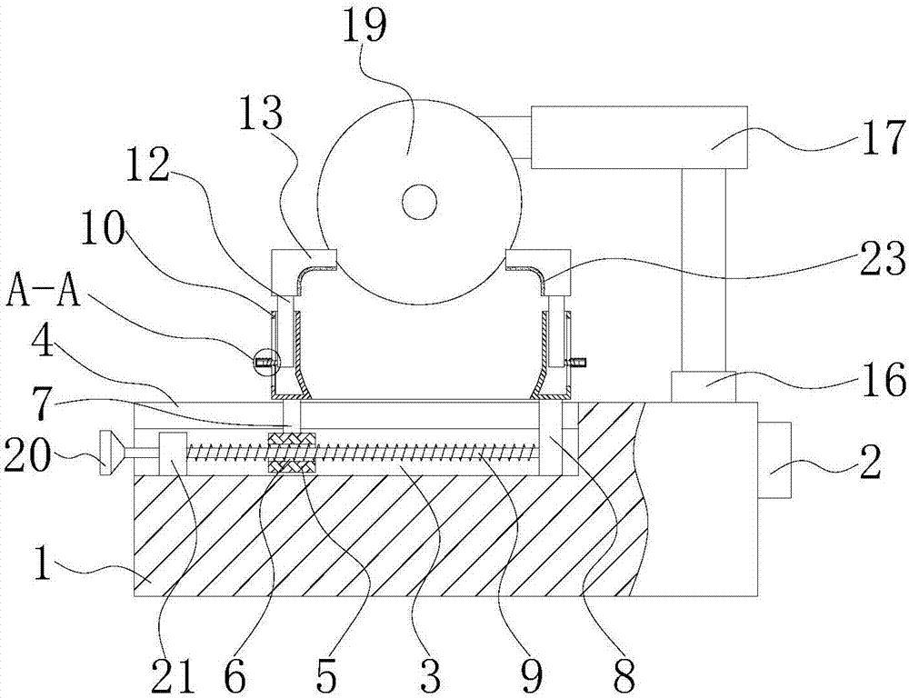
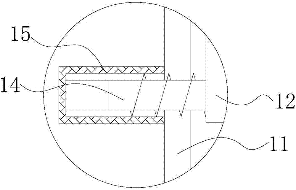
The invention discloses an efficient pipe cutting machine. The efficient pipe cutting machine comprises a base. A controller is fixedly connected to the right side of the base. A sliding groove is formed in the left side of the base. The top of the base is provided with a transverse groove communicating with the sliding groove. A sliding block is slidably connected in the sliding groove. A threaded hole is formed in the left side of the sliding block. A first supporting block is fixedly connected to the top of the sliding block. A second supporting block is fixedly connected to the right side of the bottom of an inner cavity of the sliding groove. The top of the first supporting block and the top of the second supporting block both penetrate through the transverse groove and extend to the outside of the transverse groove. A first threaded rod is movably connected to the position, located in the sliding groove, of the left side of the second supporting block. According to the efficient pipe cutting machine, rotation of the first threaded rod can drive the sliding block to transversely move, so the first supporting block and clamping plates can be driven to transversely move; and thus, the distance between the two clamping plates can be adjusted, a plurality of pipes can be clamped, the cutting efficiency of the pipes is greatly improved, and using by a user is more convenient.
Description
technical field [0001] The invention relates to the technical field of metal processing, in particular to a high-efficiency pipe cutting machine. Background technique [0002] The metal processing device is a device for processing metal, including cutting equipment, grinding equipment, stamping equipment, etc. The cutting device is needed in the pipe processing process. The existing pipe cutting device has poor cutting accuracy. When it is necessary to cut a certain length of pipe, It is also necessary to measure with a measuring tool, and the operation is cumbersome. For example, the Chinese patent discloses a "pipe cutting machine", the patent number is: CN106270735A, which includes a base, a groove, a chute, a support column, a slide block, a cutting device, and a baffle , threaded holes, threaded rods, fixed columns, protrusions, hydraulic pumps, support frames, cutting knives, support blocks and piston rods, the side of the base adjacent to the baffle is recessed inward...
Claims
Application Information
Patent Timeline
Application Date:The date an application was filed.
Publication Date:The date a patent or application was officially published.
First Publication Date:The earliest publication date of a patent with the same application number.
Issue Date:Publication date of the patent grant document.
PCT Entry Date:The Entry date of PCT National Phase.
Estimated Expiry Date:The statutory expiry date of a patent right according to the Patent Law, and it is the longest term of protection that the patent right can achieve without the termination of the patent right due to other reasons(Term extension factor has been taken into account ).
Invalid Date:Actual expiry date is based on effective date or publication date of legal transaction data of invalid patent.

