Planar dual-reflection array antenna

An array antenna and double-reflection technology, applied in the field of communication, can solve the problem of high antenna profile

Active Publication Date: 2016-03-23
BEIJING INST OF RADIO METROLOGY & MEASUREMENT
View PDF2 Cites 14 Cited by
  • Summary
  • Abstract
  • Description
  • Claims
  • Application Information

AI Technical Summary

Problems solved by technology

[0005] In view of this, the embodiment of the present application provides a planar dual-reflection

Method used


Image

  • Planar dual-reflection array antenna
  • Planar dual-reflection array antenna
  • Planar dual-reflection array antenna

Examples


Embodiment Construction

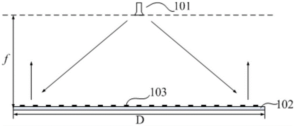
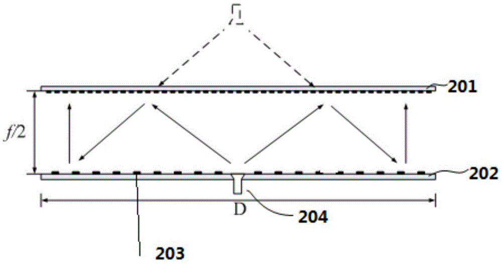
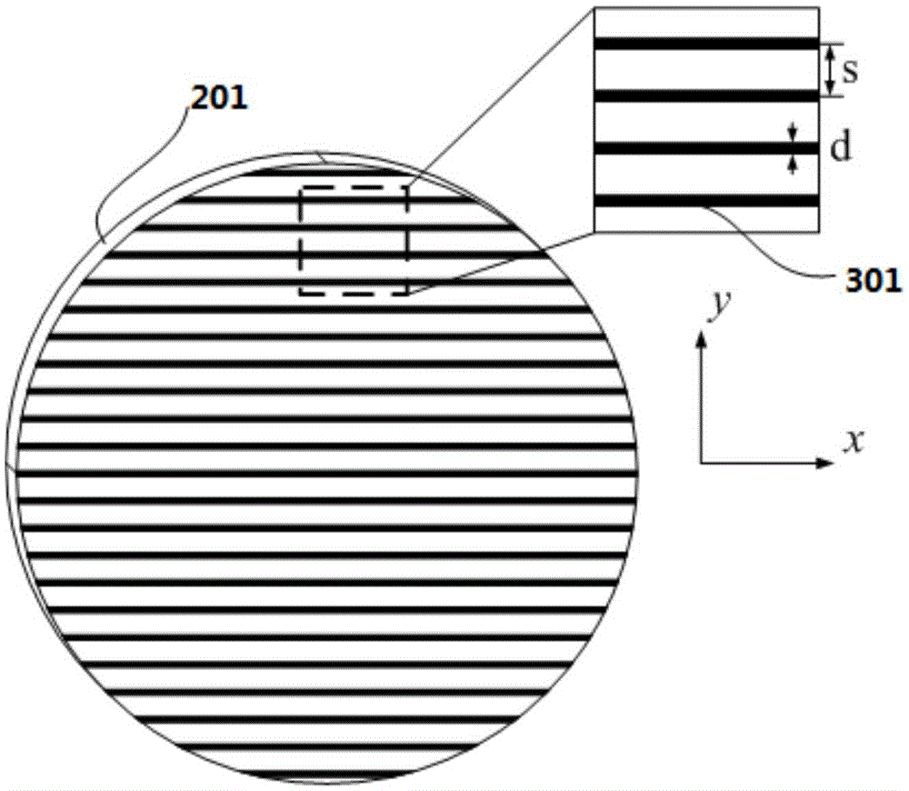
[0020] In order to achieve the purpose of the present invention, an embodiment of the present invention provides a planar double-reflect array antenna, the planar double-reflect array antenna includes a polarization selective layer, a main reflecting surface, and a microstrip patch located on the main reflecting surface The unit and the feed source on the same side as the main reflection surface, the polarization selection layer is used to reflect the electromagnetic wave signal emitted by the feed source to the main reflection surface; the microstrip patch unit is used The phase compensation is performed on the electromagnetic wave signal reaching the main reflection surface, the polarization direction of the electromagnetic wave signal is changed, and the electromagnetic wave signal is transmitted through the polarization selection layer to form a composite beam pointing to a set direction. In this way, the planar double reflectarray antenna halves the profile height of the t...


PUM


Abstract

The invention discloses a planar dual-reflection array antenna. The planar dual-reflection array antenna comprises a polarization selection layer, a main reflection surface, a microstrip patch unit positioned on the main reflection surface and a feed source on the same side with the main reflection surface, wherein the polarization selection layer is used for reflecting an electromagnetic wave signal emitted by the feed source to the main reflection surface; and the microstrip patch unit is used for performing phase compensation on the electromagnetic wave signal reached the main reflection surface and changing the polarization direction of the electromagnetic wave signal to enable the electromagnetic wave signal to transmit to the polarization selection layer to form a synthesized wave beam with an assigned setting direction. Therefore, the section profile height of the planar dual-reflection array antenna is half of that of the conventional reflection array antenna, so that the problem of relatively high section of the antenna is effectively avoided; and meanwhile, the polarization direction of the electromagnetic wave signal is adjusted by the microstrip patch unit of the planar dual-reflection array antenna, so that the performance of the planar dual-reflection array antenna is effectively improved.

Description

technical field [0001] The invention relates to the technical field of communications, in particular to a planar double-reflection array antenna. Background technique [0002] Runway foreign object debris, also known as airport runway FOD (English: Foreign Object Debris), is one of the biggest risk factors that civil aviation aircraft face during the take-off and landing phases. The hazards it causes include aircraft engine damage, tire burst, and aircraft body damage. [0003] In order to avoid the harm caused by foreign object debris on the airport runway, it is necessary to set up an airport runway foreign object debris detection system near the airport runway. At present, in practical application, the foreign object debris detection system on the airport runway is composed of a radar detection system. The working principle of the radar detection system is: the radar equipment emits electromagnetic waves of a specific frequency, and determines the spatial position infor...

Claims


Application Information

Patent Timeline
IPC IPC(8): H01Q1/38H01Q13/08H01Q19/10H01Q21/24
CPCH01Q1/38H01Q13/08H01Q19/10H01Q21/245
Inventor 费鹏郭洧华温鑫张鹏
Owner BEIJING INST OF RADIO METROLOGY & MEASUREMENT
Why Eureka
Try Eureka