Positioning clamp

A technology for positioning fixtures and clamping blocks, applied in positioning devices, clamping, manufacturing tools, etc., can solve the problems of deviation in cutting dimensions, easy loosening of steel pipes, poor stability, etc., to prevent dimensional deviation, improve stability, and design reasonable effect

Inactive Publication Date: 2016-03-30
TIANJIN SHENGLIDA MECHANICAL EQUIP CO LTD
View PDF0 Cites 11 Cited by
  • Summary
  • Abstract
  • Description
  • Claims
  • Application Information

AI Technical Summary

Problems solved by technology

At present, steel pipes need to be positioned and clamped before cutting, but the existing positioning fixtures are usually less stable, and the steel pipes are easy to loosen during the cutting process, resulting in deviations in the cut size

Method used


Image

  • Positioning clamp

Examples


Embodiment Construction

[0015] Specific embodiments of the present invention will be described in detail below in conjunction with the accompanying drawings.

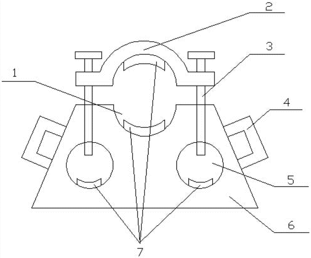
[0016] like figure 1 As shown, a positioning fixture includes a base 6, an upper clamping block 2 and a fastening bolt 3, the base 6 is a trapezoidal structure, the upper end of the base 6 is provided with an arc-shaped groove 1, and the upper clamping block 2 is provided with a downward facing The lower groove, the arc groove 1 has the same radian as the lower groove, screw holes are provided on both sides of the upper clamping block 2, the fastening bolts 3 are respectively screwed into the screw holes, and the base 6 is provided with two placement holes 5. The placement hole 5 is located directly below the screw hole, and the fastening bolt 3 extends into the placement hole 5 .

[0017] Arc-shaped rubber pads 7 are provided in the arc-shaped groove 1 and at the bottom of the placement hole 5 . An arc-shaped rubber pad 7 is arranged in the...


PUM


Abstract

The invention discloses a positioning clamp which comprises a base, an upper clamping block and fastening bolts. An arc-shaped groove is formed in the upper end of the base. The upper clamping block is provided with a lower groove facing downwards. The radian of the arc-shaped groove is equal to that of the lower groove. Screw holes are formed in the two sides of the upper clamping block. The fastening bolts are screwed in the screw holes respectively. Two storing holes are formed in the base and located under the screw holes. The fastening bolts stretch into the storing holes. The positioning clamp has the advantages that the design is reasonable, the stability of steel pipe clamping is improved, and dimensional deviation caused by looseness of a steel pipe in the cutting process is prevented.

Description

technical field [0001] The invention belongs to the field of positioning fixture equipment, and in particular relates to a positioning fixture. Background technique [0002] With modern production, the demand for steel pipes in the market is increasing day by day. For different purposes, the size of the steel pipe required is also different, which requires cutting the steel pipe. At present, steel pipes need to be positioned and clamped before cutting, but the existing positioning fixtures are usually less stable, and the steel pipes are easy to loosen during the cutting process, resulting in deviations in the cut size. Contents of the invention [0003] The problem to be solved by the present invention is to provide a positioning fixture which can solve the above problems. [0004] In order to solve the above technical problems, the technical solution adopted in the present invention is: a positioning fixture, including a base, an upper clamping block and fastening bolt...

Claims


Application Information

Patent Timeline
Patent Type & Authority Applications(China)
IPC IPC(8): B23D33/02B23Q3/06
CPCB23D33/02B23Q3/064
Inventor 王亚高
Owner TIANJIN SHENGLIDA MECHANICAL EQUIP CO LTD
Why Eureka
Try Eureka