Waveform control circuit for alternate current argon arc welding machine

A technology for controlling circuits and argon arc welding machines, applied in arc welding equipment, manufacturing tools, welding equipment, etc., can solve the problems of slow welding speed, reduced welding strength, unsatisfactory cleaning effect, etc., and achieve the reduction of welding time , increase the duty cycle, and enhance the cleaning effect

Active Publication Date: 2016-03-30
SHANGHAI WTL WELDING EQUIP MFG CO LTD
View PDF8 Cites 8 Cited by
  • Summary
  • Abstract
  • Description
  • Claims
  • Application Information

AI Technical Summary

Benefits of technology

This patented technology allows for independent regulation of an alternating current (AC) signal's frequency during each period between two voltage levels called on-state or off- state. By doing this, the power supply system has better efficiency compared to previous methods while also increasing its ability to remove impurities from the workpiece being processed. Additionally, reducing the duration of these periods results in less heat input into the electrode wire used to generate electricity causing damage due to overheated spark plugs. Overall, this new method enhances both cleaner quality and faster cutting speeds without sacrificing protective fuses needed inside the equipment itself.

Problems solved by technology

This patented technical problem addressed in this patents relates to improving the performance of AC gas torches while maintaining stable operation under different conditions or operating modes.

Method used


Image

  • Waveform control circuit for alternate current argon arc welding machine
  • Waveform control circuit for alternate current argon arc welding machine
  • Waveform control circuit for alternate current argon arc welding machine

Examples


Embodiment Construction

[0028] Specific embodiments of the present invention will be described in detail below in conjunction with the accompanying drawings.

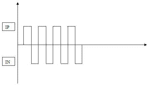
[0029] The waveform of the AC argon arc welding machine of the prior art is as figure 1 as shown, figure 1 IP is a positive wave, IN is a negative wave, the amplitude and frequency of the positive and negative waves are the same, and the positive and negative waves cannot be adjusted separately.

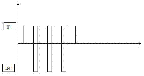
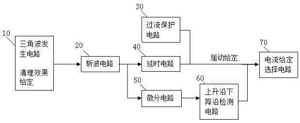
[0030] The principle of the present invention is to use an adjustable resistor to input the set cleaning effect, select the duty cycle of the square wave according to the cleaning effect, and determine the frequency according to the rising edge and falling edge of each driving waveform and two complementary square wave driving signals. Choose different current output, so as to achieve the purpose of different positive and negative output current of AC argon arc welding machine. Increase the output amplitude of AC negative, so that the cleaning effe...


PUM


Abstract

The invention discloses a waveform control circuit for an alternate current argon arc welding machine. The waveform control circuit is used for adjusting the positive and negative amplitude of square waves of the alternate current argon arc welding machine and is characterized by comprising a triangular wave generation circuit, a chopper circuit, a time delay circuit, a differentiating circuit, a rising edge and falling edge detection circuit and a given current selection circuit; the triangular wave generation circuit is used for generating a triangular wave; the chopper circuit is connected to the output end of the triangular wave generation circuit and is used for outputting the square wave with the output duty ratio adjustable; the time delay circuit is connected to the output end of the chopper circuit and is used for generating two complementary square wave drive signals; the differentiating circuit is connected to the output end of the chopper circuit and generates signals P1 and P2; the rising edge and falling edge detection circuit judges the rising edges and the falling edges of the square wave drive signals according to the signals P1 and P2; the given current selection circuit outputs a positive wave output control signal and a negative wave output control signal according to the square wave drive signals and the rising edges and the falling edges of the square wave drive signals.

Description


Claims


Application Information

Patent Timeline
Owner SHANGHAI WTL WELDING EQUIP MFG CO LTD
Why Eureka
Try Eureka