Power controller for supercapacitor

a supercapacitor and power controller technology, applied in the direction of dynamo-electric converter control, motor/generator/converter stopper, dc-dc conversion, etc., can solve the problems of inability to regulate the working conditions of the motor, such as rotational speed and power output, and the supercapacitors have relatively low volume and capacity, so as to prevent the excess voltage and high voltage

Inactive Publication Date: 2015-10-29
NANJING SUPER SCI & TECH INDAL
View PDF10 Cites 0 Cited by
  • Summary
  • Abstract
  • Description
  • Claims
  • Application Information

AI Technical Summary

Benefits of technology

The power controller for supercapacitors described in this patent has several advantages. It allows for a smoother and more stable operation of the motor and the supercapacitor under various working conditions. It also allows for an increased output of energy from the supercapacitor. The number of supercapacitors can be adjusted through the switch, and the voltage-stabilizing circuit ensures the motor operates at its rated conditions most of the time, preventing excess voltage. Overall, the power controller improves the performance of the supercapacitor system.

Problems solved by technology

However, compared with chemical cells, supercapacitors have relatively low volume and capacity, as well as the following disadvantages: 1. the terminal voltage change rate of chemical cells is often less than 15%, while that of a supercapacitor often reaches 80-90% of the rated value; 2. the initial voltage of a supercapacitor cannot be too high, or the motor will malfunction; and 3. the working conditions of the motor, such as rotational speed and power output, cannot be regulated.

Method used


Image

  • Power controller for supercapacitor
  • Power controller for supercapacitor

Examples


Embodiment Construction

[0015]For further illustrating the invention, experiments detailing a power controller for supercapacitors are described below. It should be noted that the following examples are intended to describe and not to limit the invention.

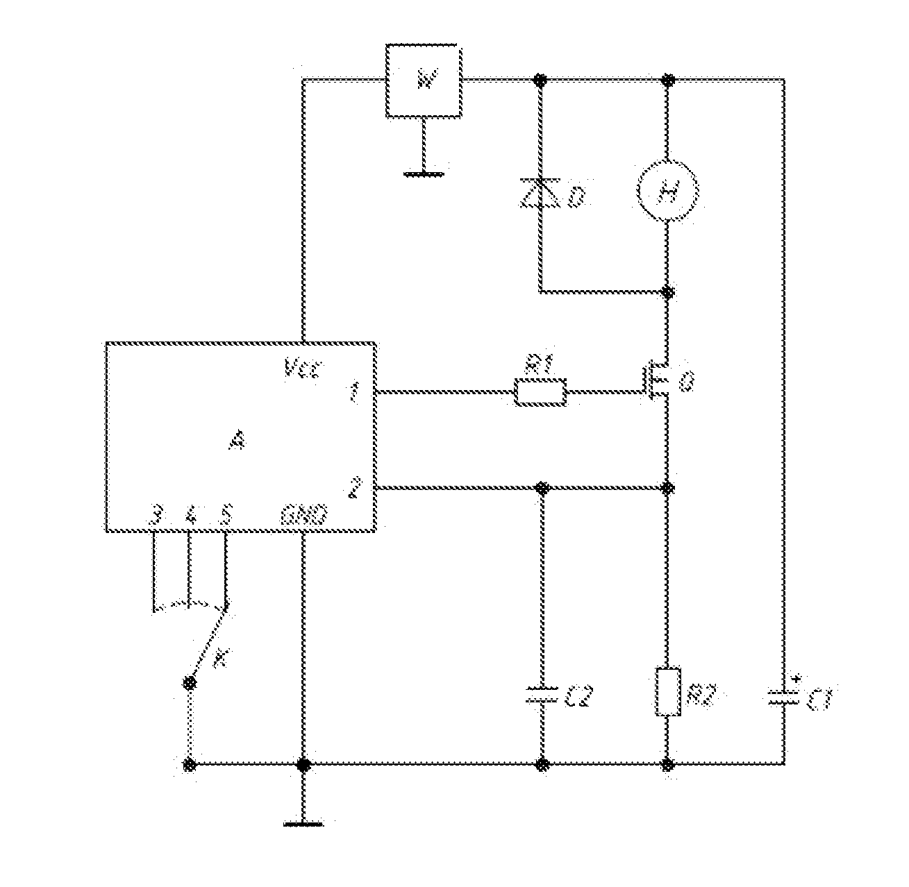
[0016]As shown in FIG. 1, a power controller for supercapacitors comprises a supercapacitor C1, a motor H, a switching tube Q, an annunciator A, an output resistor R1, a sampling resistor R2, a filter capacitor C2, a voltage-stabilizing circuit W, a fly-wheel diode D, and a switch K. The supercapacitor C1, the motor H, the switching tube Q and the sampling resistor R2 are serially connected to form a main working circuit. A signal output end 1 of the annunciator A is connected to a trigger electrode of the switching tube Q via the output resistor R1; a sampling end 2 of the annunciator A is connected to the sampling resistor R2; the motor H is connected in parallel to the fly-wheel diode D; the sampling resistor R2 is connected in parallel to the filter ca...


PUM


Abstract

A power controller, including a supercapacitor, a motor, a switching tube, an annunciator, an output resistor, a sampling resistor, a filter capacitor, a voltage-stabilizing circuit, a fly-wheel diode, and a switch. The supercapacitor, the motor, the switching tube and the sampling resistor are connected in series to form a main working circuit. The signal output end of the annunciator is connected to a trigger electrode of the switching tube via the output resistor. The sampling end of the annunciator is connected to the sampling resistor. The motor is connected in parallel to the fly-wheel diode. The sampling resistor is connected in parallel to the filter capacitor. The Vcc end of the annunciator is connected to the supercapacitor via the voltage-stabilizing circuit. The state control ends of the annunciator are connected to the GND or Vcc of the annunciator via the switch.

Description

CROSS-REFERENCE TO RELATED APPLICATIONS[0001]This application is a continuation-in-part of International Patent Application No. PCT / CN2014 / 000591 with an international filing date of Jun. 17, 2014, designating the United States, now pending, and further claims priority benefits to Chinese Patent Application No. 201410118400.2 filed Mar. 27, 2014. The contents of all of the aforementioned applications, including any intervening amendments thereto, are incorporated herein by reference. Inquiries from the public to applicants or assignees concerning this document or the related applications should be directed to: Matthias Scholl P.C., Attn.: Dr. Matthias Scholl Esq., 245 First Street, 18th Floor, Cambridge, Mass. 02142.BACKGROUND OF THE INVENTION[0002]1. Field of the Invention[0003]The invention relates to a power controller for supercapacitors.[0004]2. Description of the Related Art[0005]Supercapacitors contain a large number of charges and thus can be used as a power supply for small...

Claims


Application Information

Patent Timeline
Patent Type & Authority Applications(United States)
IPC IPC(8): H02P7/06
CPCH02P7/06H02M3/156Y02E60/16H02J7/00
Inventor XIANG, KEWEIGE, QICONG
Owner NANJING SUPER SCI & TECH INDAL
Why Eureka
Try Eureka