Telescopic mechanism with simple and detachable roller wheel device

A telescopic mechanism and detachable technology, which is applied in the direction of wheels, transportation and packaging, railway car body parts, etc., can solve the problems of troublesome disassembly, damage of rollers, and reduce the effect of maintenance and other problems, so as to achieve convenient disassembly and installation, prevent derailment, improve Effects for changing speed and effects

Active Publication Date: 2016-03-30
SUZHOU PINFA ELECTROMECHANICAL TECH CO LTD
View PDF6 Cites 10 Cited by
  • Summary
  • Abstract
  • Description
  • Claims
  • Application Information

AI Technical Summary

Problems solved by technology

[0002] In the existing transmission shaft mechanism, the rollers at both ends of the shaft body are fixed to realize rolling, and the distance between the shaft body and the two rollers will not move, that is, the distance is fixed, and the track will move between the wheels when turning. The clamping position is generated, so that when the trolley using this mechanism is running on the track, it is easy to derail when the trolley turns, causing accidents
[0003] Moreover, the existing roller structure generally adopts the axial through hole in the middle of the wheel body to fix the bearing through interference fit, and then fix it on the bearing through the rotating shaft, and the wearing part of the roller is the bearing, and because the bearing It is fixed on the wheel body through interference fit, which makes its disassembly very troublesome, thus greatly reducing the effect of its maintenance, and the improper disassembly of the bearing is easy to damage the roller, so the roller needs to be replaced, which increases the maintenance cost

Method used


Image

  • Telescopic mechanism with simple and detachable roller wheel device
  • Telescopic mechanism with simple and detachable roller wheel device
  • Telescopic mechanism with simple and detachable roller wheel device

Examples


Embodiment Construction

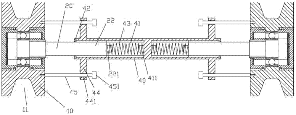
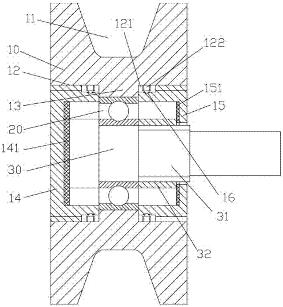
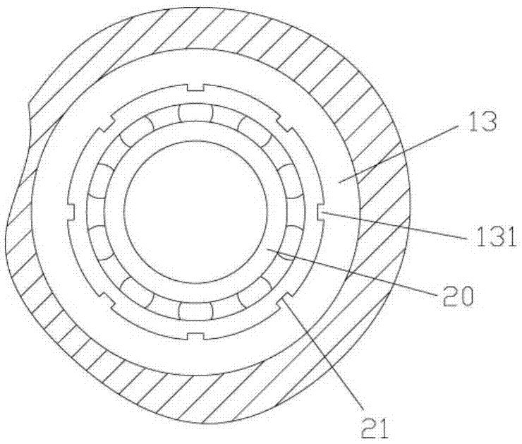
[0018] Examples, see e.g. Figure 1 to Figure 3 As shown, a telescopic mechanism adopting a simple detachable roller device includes two wheel bodies 10 and a middle connecting shaft body 40. The outer wall of the wheel body 10 has a wheel groove 11, and the middle part of the wheel body 10 has an axial The through hole 12 has a connecting raised ring 13 on the middle side wall of the axial through hole 12, and a plurality of raised strips 131 are provided on the inner side wall of the connecting raised ring 13, and the bearing 20 is inserted into the connecting raised ring 13, The raised bar 131 is inserted into the corresponding bar-shaped groove 21 on the outer side wall of the outer ring of the bearing 20, the rotating shaft 30 is fixed in the inner ring of the bearing 20, and the inner side walls at both ends of the axial through hole 12 have Internal thread, the outer end cap 14 and the inner end cap 15 are respectively screwed into the internal thread at the end of the ...


PUM


Abstract

The invention discloses a telescopic mechanism with a simple and detachable roller wheel device. The telescopic mechanism comprises two wheel bodies and a middle connecting shaft body, wherein the outer wall of each wheel body is provided with a wheel groove; an axial through hole is formed in the middle of each wheel body; the middle lateral wall of each axial through hole is provided with a connecting protruding ring; the inner wall of each connecting protruding ring is provided with a plurality of protruding strips; a bearing is inserted into each connecting protruding ring; the protruding strips are inserted into corresponding strip-shaped grooves in the outer wall of outer rings of the corresponding bearings; a rotary shaft is fixed in the inner ring of each bearing, and the connecting end of each rotary shaft is provided with a spline shaft part; the two ends of the middle connecting shaft body are provided with spline holes, and the spline shaft parts are inserted into the corresponding spline holes; end covers are fixed at the two ends of the middle connecting shaft body, and the connecting ends of the rotary shafts are inserted into the end covers; a buffering spring is arranged between each spline shaft part and the bottom end of the corresponding spline hole. The telescopic mechanism with the simple and detachable roller wheel device can prevent derailing during running, and meanwhile the bearings in the wheel bodies are convenient to dismount and mount.

Description

Technical field: [0001] The invention relates to the technical field of roller device equipment, and more specifically relates to a telescoping mechanism for a simple and detachable roller device. Background technique: [0002] In the existing transmission shaft mechanism, the rollers at both ends of the shaft body are fixed to realize rolling, and the distance between the shaft body and the two rollers will not move, that is, the distance is fixed, and the track will move between the wheels when turning. The clamping position is generated, so that when the trolley using this mechanism is running on the track, it is easy to derail when the trolley turns, causing an accident. [0003] And what the existing roller structure generally adopts is that the axial through hole that the middle part of the wheel has has clamps and fixes the bearing by interference fit, and then is fixed on the bearing through the rotating shaft, and the wearing part of the roller is the bearing, and b...

Claims


Application Information

Patent Timeline
Patent Type & Authority Applications(China)
IPC IPC(8): B60B35/10B61F9/00
CPCB60B35/109B61F9/00
Inventor 洪汝频杨爱林
Owner SUZHOU PINFA ELECTROMECHANICAL TECH CO LTD
Why Eureka
Try Eureka