
Quad tilt-rotor aircraft

A technology for tilting quadrotors and aircraft, which is applied in the field of aircraft and can solve the problems of complex, cumbersome, and difficult to implement mechanical mechanisms.

Inactive Publication Date: 2016-03-30
珞石(北京)科技有限公司
View PDF8 Cites 7 Cited by
  • Summary
  • Abstract
  • Description
  • Claims
  • Application Information

AI Technical Summary

Problems solved by technology

[0007] CN103693194A proposes that in the cruising stage, the rear end of the fuselage where the empennage is located is rotated 90° around the fuselage axis, so that the front wing and the rear wing form a "cross" shape, which of course can eliminate the influence of the slipstream generated by the front wing on the rear wing , but the mechanical mechanism required to rotate the tail end of the fuselage by 90 degrees will be very complicated and cumbersome, and it is still difficult to realize

Method used

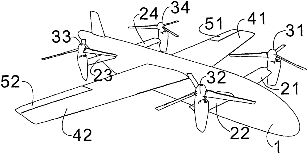
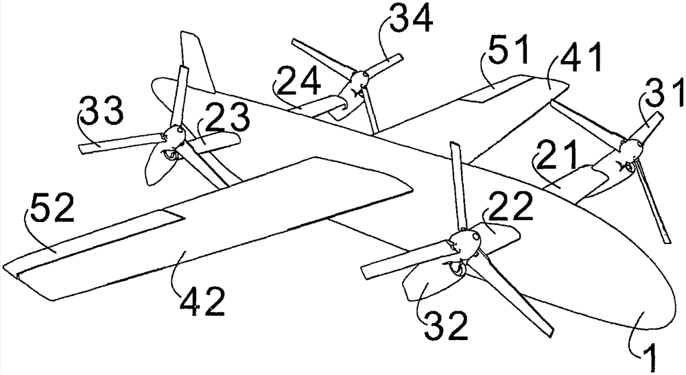
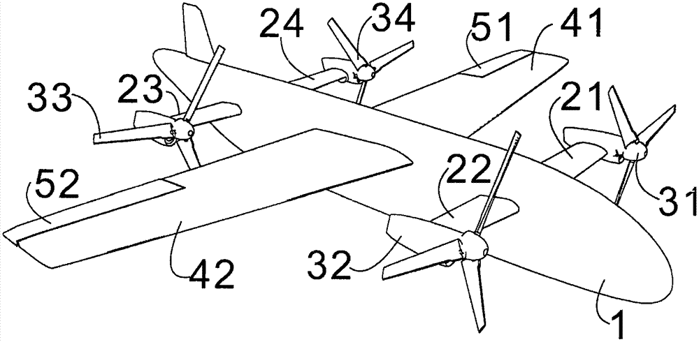

Image

  • Quad tilt-rotor aircraft
  • Quad tilt-rotor aircraft
  • Quad tilt-rotor aircraft

Examples


Embodiment Construction

[0019] In order to facilitate the understanding, it is necessary to explain the "wing span" before starting the description of the present invention. In this field, the wing span refers to the distance between the left and right wing tips of the aircraft's wings, so the main wing span refers to the distance between the wing tips of the two main wings, and the front wing span refers to the distance between the wing tips of the two front wings. The rear wing span refers to the distance between the wing tips of the two rear wings.

[0020] Such as Figure 1~3 As shown, a tilting quad-rotor aircraft of the present invention includes a fuselage 1 with front wings 21 (22), rear wings 23 (24) and main wings 41 (42) symmetrically arranged on both sides of the fuselage 1. The main wing is located between the front wing and the rear wing, and the main wing span is equal to the length of the fuselage. The front and rear wing spans are both 0.2 to 0.33 times the main wing span, especially 0...


PUM


Abstract

The invention provides a quad tilt-rotor aircraft, which relates to an aircraft and aims at providing a quad-rotor aircraft with stable operation and firm structure. According to the invention, the quad tilt-rotor aircraft comprises an aircraft body, wherein a front wing and a rear wing are arranged on the two sides of the aircraft body; motors are respectively arranged at the outer ends of the front wing and the rear wing; rotors are fixed on output shafts of the motors; the motors are connected with the corresponding front wing or the corresponding rear wing through shafts; main wings are also arranged on the two sides of the aircraft body; the main wings are arranged between the front wing and the rear wing; and the span lengths of the front wing and the rear wing are both less than those of the main wings.

Description

Technical field [0001] The invention relates to an aircraft, in particular to a four-rotor aircraft. Background technique [0002] Tilting quadrotor is a future aircraft that attempts to integrate the advantages of quadrotor vertical take-off and landing / hovering and high-speed cruise of fixed-wing aircraft. During take-off / landing, the four rotor shafts remain vertical to generate upward lift so that the aircraft can overcome gravity and make the aircraft take off and land smoothly; when cruising, the four rotor shafts are parallel to the fuselage axis, generating forward pulling force, and the wings generate lift Overcome gravity and make the aircraft fly at high speed; in the transition phase, the rotor axis slowly tilts 90°, and the rotation speed of each rotor is given by the control algorithm to keep the attitude of the aircraft stable. At the same time, the horizontal speed of the aircraft is gradually increasing. , Make the aircraft transition smoothly. [0003] However, ...

Claims


Application Information

Patent Timeline
Patent Type & Authority Applications(China)
IPC IPC(8): B64C27/28B64C27/26
CPCB64C27/28B64C27/26
Inventor 王凯
Owner 珞石(北京)科技有限公司
Learn More