
Quick disassembly and assembly structure of holder and unmanned aerial vehicle

A technology of drones and gimbals, applied in the field of drones, can solve problems such as difficult operation by ordinary users, cumbersome disassembly process, etc., and achieve the effect of quick disassembly, simplified disassembly process, and firm assembly

Active Publication Date: 2016-03-30
XIAOMI INC +1
View PDF5 Cites 11 Cited by
  • Summary
  • Abstract
  • Description
  • Claims
  • Application Information

AI Technical Summary

Problems solved by technology

[0003] However, the pan / tilt structure in the related art is often installed with screws, etc., resulting in a very cumbersome disassembly process, which is not easy for ordinary users to operate.

Method used


Image

  • Quick disassembly and assembly structure of holder and unmanned aerial vehicle
  • Quick disassembly and assembly structure of holder and unmanned aerial vehicle
  • Quick disassembly and assembly structure of holder and unmanned aerial vehicle

Examples


Embodiment 1

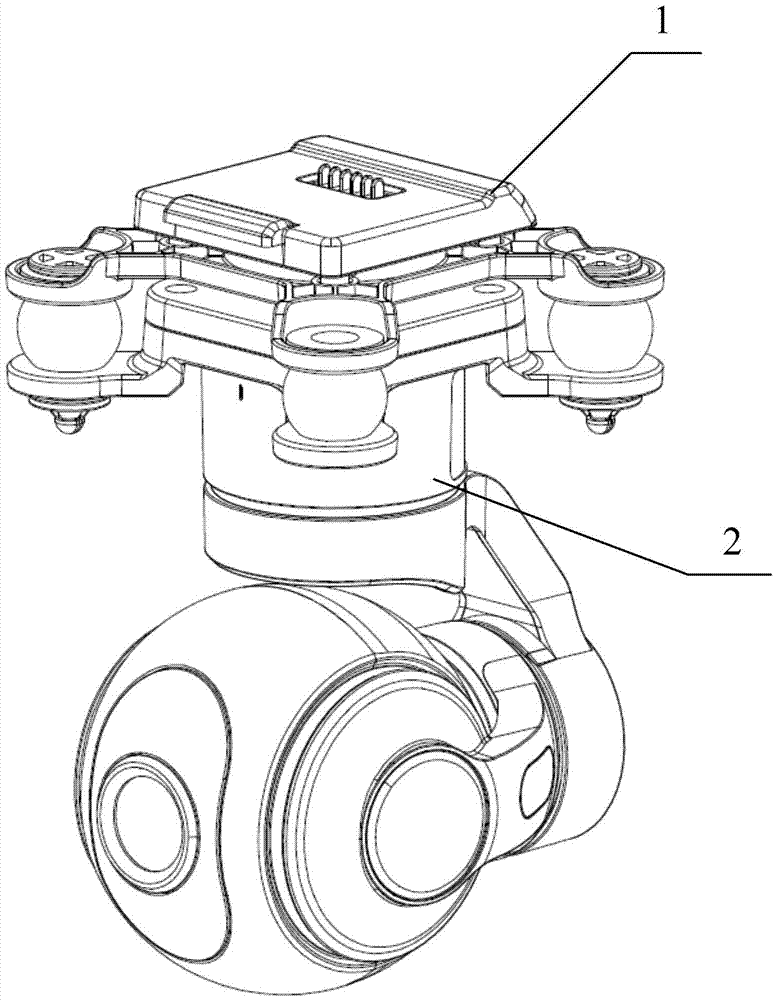
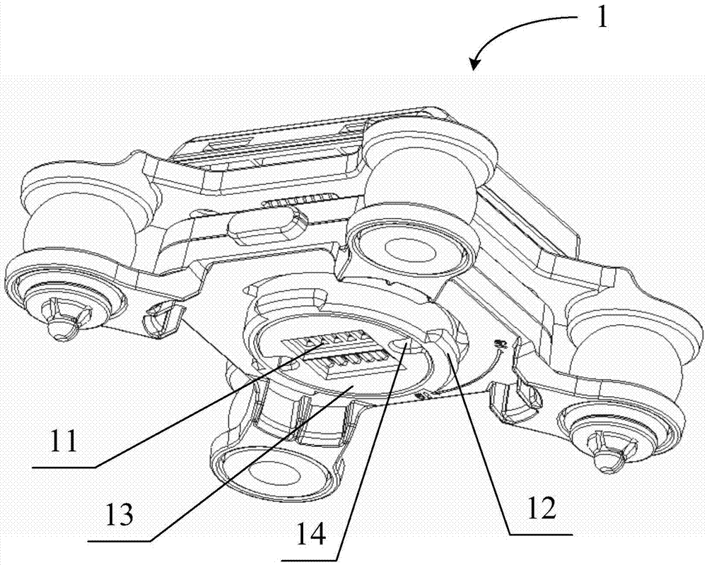
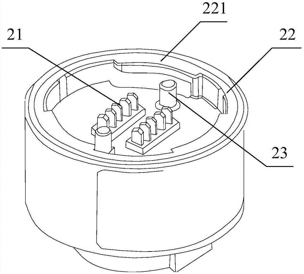
[0050] In an exemplary embodiment, the hooking part may include: figure 2 At least one protrusion 12 at the bottom of the shown shock-absorbing connection structure 1 and image 3 At least one notch 221 is formed on the annular protrusion 22 at the top of the platform structure 2 shown.

[0051] Among them, such as figure 2 As shown, the protrusion 12 is located on the bottom outer wall of the shock-absorbing connection structure 1 and is arranged along the radial direction at the corresponding position; at the same time, as image 3 As shown, the annular protrusion 22 is located at the top inner wall of the platform structure 2 and is set along the radial direction at the corresponding position; Set in the horizontal direction.

[0052] Since the power supply port 11 and the power interface 21 are respectively located inside the shock-absorbing connection structure 1 and the cloud platform structure 2, and the protrusion 12 and the notch 221 are respectively located at t...

Embodiment 2

[0058] In another exemplary embodiment, similar to Embodiment 1, the hooking part may include: at least one protrusion arranged radially on the top outer wall of the platform structure 2 , and at least one protrusion along the bottom inner wall of the shock-absorbing connection structure 1 . A radially arranged annular protrusion, and at least one notch is provided on the annular protrusion; wherein, the protrusion can pass through when the pan-tilt structure 2 forms a first preset rotation angle relative to the shock-absorbing connection structure 1 pass through the notch, and the protrusion can hang on the upper end surface of the annular protrusion where the notch is not provided when the pan-tilt structure 2 forms a second preset rotation angle relative to the shock-absorbing connection structure 1 . Since only the positions of the protrusion and the notch are reversed, the rest of the structure and matching process are the same as those in Embodiment 1, so no more details ...


PUM


Abstract

The invention discloses a quick disassembly and assembly structure of a holder and an unmanned aerial vehicle; and the quick disassembly and assembly structure of the holder is used for quick disassembly and assembly of the holder structure and the belonged unmanned aerial vehicle. The quick disassembly and assembly structure of the holder comprises a hanging part; when a first preset rotating angle formed by the holder structure corresponding to a vibration reducing connecting structure is failed, the hanging part enables a power supply interface to be connected with a power supply interface; and after the power supply interface is connected with the power supply interface, and a second preset rotating angle formed by the holder structure corresponding to the vibration reducing connecting structure is effective, the hanging part limits the holder structure to move in the vertical direction. The quick disassembly and assembly structure of the holder further comprises a locking part; when the hanging part is effective, the locking part can lock relative positions between the holder structure and the vibration reducing connecting structure to limit the rotation of the holder structure in the horizontal direction.

Description

technical field [0001] The present disclosure relates to the technical field of unmanned aerial vehicles, in particular to a quick disassembly and assembly structure of a platform and an unmanned aerial vehicle. Background technique [0002] The gimbal is a supporting device for installing and fixing the camera, and can drive the camera to adjust the preset direction to meet the needs of different shooting angles. During the application process, sometimes it is necessary to disassemble and reinstall the pan / tilt structure for individual application or other purposes. [0003] However, the pan / tilt structure in the related art is often installed with screws, etc., resulting in a very cumbersome disassembly process, which is not easy for ordinary users to operate. Contents of the invention [0004] The present disclosure provides a quick disassembly and assembly structure of a platform and an unmanned aerial vehicle, so as to solve the deficiencies in related technologies. ...

Claims


Application Information

Patent Timeline
Patent Type & Authority Applications(China)
IPC IPC(8): B64D47/08
CPCB64D47/08
Inventor 伍沧浪杨容涛陈育辉蔡炜叶华林
Owner XIAOMI INC
Learn More