
Segmented self-traveling type cast-in-place beam hydraulic inner mould and mould erecting and demoulding method thereof

A cast-in-place beam, self-propelled technology, applied in bridges, bridge construction, erection/assembly of bridges, etc., can solve the problems of high labor intensity, low efficiency, poor working environment, etc., and achieve good overall stability and good economy. Effect

Inactive Publication Date: 2016-03-30
湖南五新智能科技股份有限公司
View PDF6 Cites 6 Cited by
  • Summary
  • Abstract
  • Description
  • Claims
  • Application Information

AI Technical Summary

Problems solved by technology

[0002] At present, the internal formwork of cast-in-place box girders mostly adopts small formwork assembly structures, which are composed of formwork and formwork support systems that form the inner cavity of the box girder. The removal and dismantling are all done manually, with low efficiency, high labor intensity, poor working environment, and poor appearance quality of the produced box girder

Method used


Image

  • Segmented self-traveling type cast-in-place beam hydraulic inner mould and mould erecting and demoulding method thereof
  • Segmented self-traveling type cast-in-place beam hydraulic inner mould and mould erecting and demoulding method thereof
  • Segmented self-traveling type cast-in-place beam hydraulic inner mould and mould erecting and demoulding method thereof

Examples


Embodiment Construction

[0031] The present invention will be further described below in conjunction with drawings and embodiments.

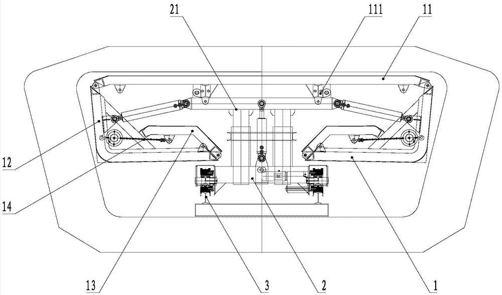
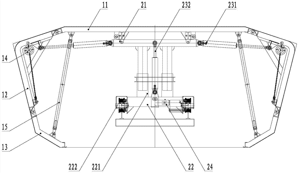
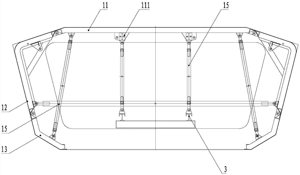
[0032] Such as figure 1 , figure 2 , image 3 , Figure 4 and Figure 5 As shown, the segmental self-propelled cast-in-place beam hydraulic inner mold provided by the present invention includes a template group, a mold moving device 2 and a track 3, and the mold moving device 2 consists of a mold moving trolley 22 and a guide set on the mold moving trolley 22. The column device 21, the lateral cylinder 231, the jacking cylinder 232, the hydraulic system 23 and the electrical system 24 are composed, the mold moving device 2 is movably connected with the segment formwork 1 through the guide column device 21, and the mold moving trolley 22 is arranged on the track 3, The formwork group is divided into several segment formworks 1 along the beam length direction, and each segment formwork 1 is composed of a top plate 11, an upper movable formwork 12 and a lower movable ...


PUM


Abstract

The invention discloses a segmented self-traveling type cast-in-place beam hydraulic inner mould and a mould erecting and demoulding method thereof. A mould moving device (2) is composed of a mould moving trolley (22), a guide column device (21), lateral oil cylinders (231), an ejecting oil cylinder (232), a hydraulic system (23) and an electrical system (24). The mould moving device (2) is movably connected with segmented formworks (1) through the guide column device (21). The mould moving trolley (22) is arranged on rails (3), and a formwork set is divided into the segmented formworks (1) in the beam length direction. Each segmented formwork (1) is composed of a top plate (11), upper movable formworks (12) and lower movable formworks (13), wherein the left end and the right end of the top plate (11) are symmetrically provided with the upper movable formworks (12) in a hinged mode, and the other ends of the upper movable formworks (12) are hinged to one ends of the lower movable formworks (13). The lateral oil cylinders (231) are connected between the upper movable formworks (12) and the mould moving device (2). Chain hoists (14) can be connected between the upper movable formworks (12) and the lower movable formworks (13). The ejecting oil cylinder (232) is installed between the guide column device (21) and the mould moving trolley (22). The mould is safe, efficient, good in overall stability and good in economic efficiency.

Description

technical field [0001] The invention relates to a cast-in-place beam inner mold, in particular to a segmented self-propelled cast-in-place beam hydraulic inner mold. The invention also relates to a vertical mold demoulding method of the segmental self-propelled cast-in-place beam hydraulic inner mold. Background technique [0002] At present, the internal formwork of cast-in-place box girders mostly adopts small formwork assembly structures, which are composed of formwork and formwork support systems that form the inner cavity of the box girder. The installation and dismantling are all realized manually, the efficiency is low, the labor intensity is high, the working environment is poor, and the appearance quality of the manufactured box girder is poor. Contents of the invention [0003] The first technical problem to be solved by the present invention is to provide a hydraulic internal mold for cast-in-place beams with safety, high efficiency, good overall stability, and...

Claims


Application Information

Patent Timeline
Patent Type & Authority Applications(China)
IPC IPC(8): E01D21/00E01D21/06
CPCE01D21/00E01D21/06
Inventor 王祥军谢亮杨波李辉蒋平文刘艳
Owner 湖南五新智能科技股份有限公司
Learn More