Rapid-distribution transfer case

A transfer case, fast technology, applied in the field of transfer case, can solve the problems of inconvenient operation, time-consuming and laborious, cumbersome implementation methods, etc., and achieve the effect of simple structure

Active Publication Date: 2016-03-30
TAIER HEAVY IND
View PDF7 Cites 0 Cited by
  • Summary
  • Abstract
  • Description
  • Claims
  • Application Information

AI Technical Summary

Problems solved by technology

figure 1 It is a schematic diagram of the structure of the existing transfer case. The transfer case includes parts such as the case body 1, the input gear shaft 2, the output shaft I3, the output shaft II4, the gear I5, and the gear II6. The transfer case passes through the input gear shaft 2 The shaft end of the shaft is connected to the power transmitted by the motor, and the power is output along two routes through gear I5 and gear II6 at the same time. The shaft ends of output shaft I3 and output shaft II4 are connected with the load shaft through a coupling. Obviously, for the two output shafts to choose Not applicable in case of alternative
And the patent CN201410565881.1 - a motor gearbox disclosed in the power closed heavy-duty coupling operating characteristics test bench, the motor gearbox has one input shaft and two output shafts, and at the same time there can only be one input shaft shaft and an output shaft are connected to the test bench system by combining and separating the intermediate coupling, that is, by disassembling and assembling the coupling, which is cumbersome, inconvenient and time-consuming

Method used


Image

  • Rapid-distribution transfer case
  • Rapid-distribution transfer case
  • Rapid-distribution transfer case

Examples


Embodiment Construction

[0018] The present invention will now be described in further detail in conjunction with the accompanying drawings. The accompanying drawings are simplified two-dimensional or three-dimensional schematic diagrams, which only illustrate the structure of the present invention in a schematic manner, and therefore only show components related to the present invention.

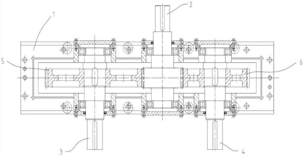
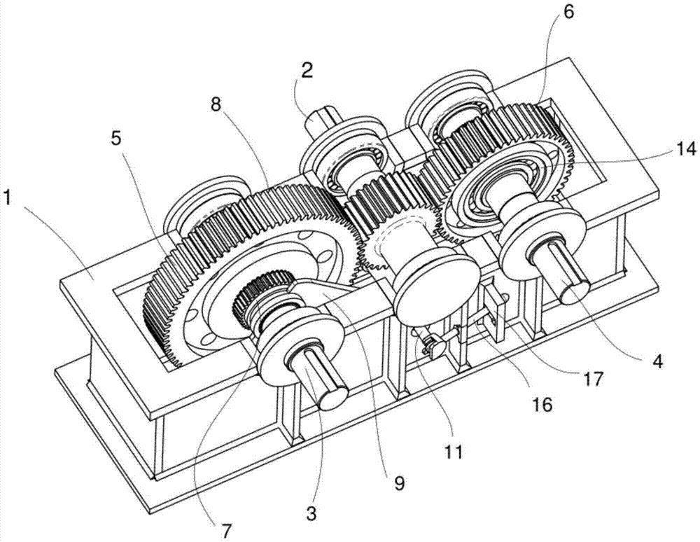
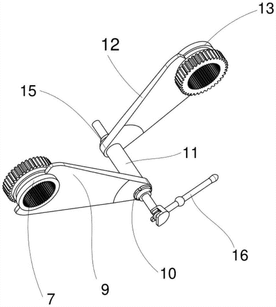
[0019] The present invention is a transfer case for rapid diversion, which includes a case body 1, an input gear shaft 2, an output shaft I3 and an output shaft II4, a gear I5, a gear II6, a bearing I8, a bearing II14, and a moving dial installed in the case body 1. Fork mechanism; bearing I8 connects gear I5 with output shaft I3, bearing II14 connects gear II6 with output shaft II4; mobile shift fork mechanism includes shift lever 16, shift fork shaft 11, shift fork mechanism I, shift fork mechanism II , the two ends of the shift fork shaft 11 are set in the holes of the front and rear plates of the box body 1, the...


PUM


Abstract

The invention discloses a rapid-distribution transfer case. The rapid-distribution transfer case comprises a case body, an input gear shaft, a first output shaft and a second output shaft, wherein the input gear shaft, the first output shaft and the second output shaft are installed in the case body. The rapid-distribution transfer case further comprises a first gear, a second gear, a first bearing, a second bearing and a movable shifting fork mechanism. The first gear is connected with the first output shaft through the first bearing, and the second gear is connected with the second output shaft through the second bearing. The movable shifting fork mechanism comprises a shifting rod, a shifting fork shaft, a first shifting fork mechanism body and a second shifting fork mechanism body. The two ends of the shifting fork shaft (11) are arranged in a hole in a front plate and a hole in a back plate of the case body, the shifting rod is connected to the shifting fork shaft, and the first shifting fork mechanism body and the output shafts achieve rapid distribution of power. It is avoided that the power of a motor is selectively output in a frequent coupling connection and separation complex manner.

Description

technical field [0001] The invention relates to a novel transfer case, in particular to a power selectable transfer case capable of rapid shunt flow transmission. technical background [0002] At present, the power transmitted from the motor generally passes through the transfer case (gearbox), and the gear on the input shaft meshes with the gears on the two output shafts to output the power, and the output end is connected to the outside world through a coupling. figure 1 It is a schematic diagram of the structure of the existing transfer case. The transfer case includes parts such as the case body 1, the input gear shaft 2, the output shaft I3, the output shaft II4, the gear I5, and the gear II6. The transfer case passes through the input gear shaft 2 The shaft end of the shaft is connected to the power transmitted by the motor, and the power is output along two routes through gear I5 and gear II6 at the same time. The shaft ends of output shaft I3 and output shaft II4 are...

Claims


Application Information

Patent Timeline
Patent Type & Authority Applications(China)
IPC IPC(8): F16H3/08F16H59/02
CPCF16H3/08F16H59/02F16H2003/0818
Inventor 张德智邹里云刘广振石珍强江长娟
Owner TAIER HEAVY IND
Why Eureka
Try Eureka