Combined-type distributing valve group

A gas distribution valve and composite technology, applied in valve details, multi-way valves, valve devices, etc., can solve problems such as complex circuit design of electronic control modules, increased vehicle power burden, and increased probability of component failure maintenance, etc., to achieve The effect of reducing the number of valve bodies and the control program

Active Publication Date: 2016-03-30
TANGTRING SEATING TECH INC
View PDF6 Cites 16 Cited by
  • Summary
  • Abstract
  • Description
  • Claims
  • Application Information

AI Technical Summary

Problems solved by technology

[0004] It can be known from the above system that when any air bag is to be inflated, the electronic control module must at least drive the control valve and the corresponding inflation valve to inflate the air bag. If multiple air bags are to be inflated at the same time, several valves must be controlled simultaneously. The circuit design of the electronic control module is complex, and the operation of several valve bodies consumes a lot of power. If the charging and exhaust system is installed in a location with limited energy, such as in a car seat, it will burden the car with electricity Increase
[0005] Furthermore, each air bag needs two valve bodies, the inflation valve and the exhaust valve, to perform the inflation and deflation action, and is equipped with a check valve to maintain the saturation after inflation. In addition, there is at least one valve on the inflation pipeline Controlling the air valve leads to an increase in the configuration space and installation cost required by the parts, and also increases the probability of parts failure repairs
[0006] In view of this, the inventor has accumulated many years of research and practical experience in related fields, and invented a compound air distribution valve group, which can perform multiple functions such as intake, inflation, backstop and exhaust for multiple groups of air bags. , in order to improve the lack of several valve bodies such as control valve, inflation valve, exhaust valve and check valve in the existing charging and exhausting system, and control them separately

Method used


Image

  • Combined-type distributing valve group
  • Combined-type distributing valve group
  • Combined-type distributing valve group

Examples


Embodiment Construction

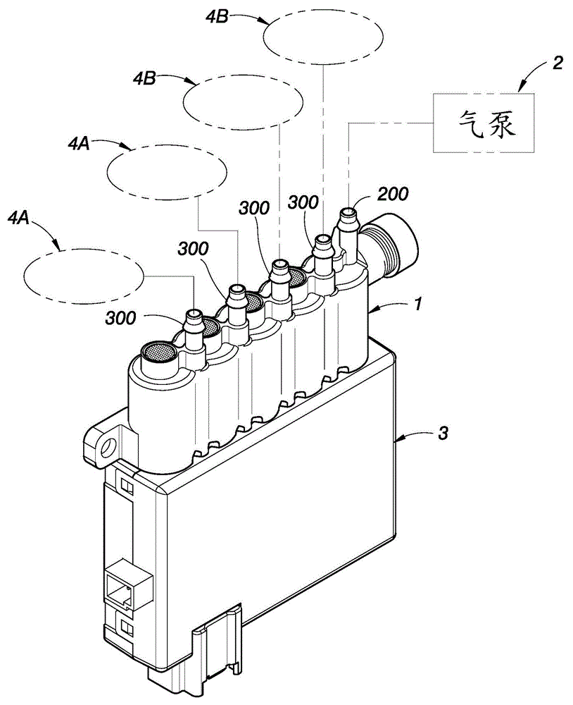
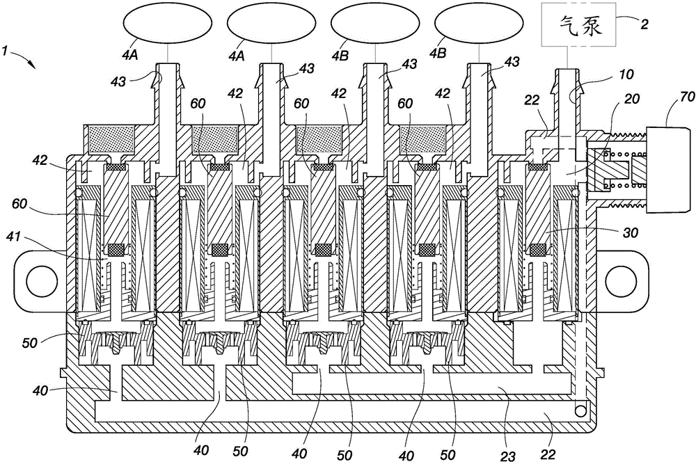
[0037] Such as Figure 1 to Figure 3 As shown, the composite gas distribution valve group 1 of the present invention is set in an inflation and exhaust system with an air pump 2 and an electronic control module 3 to inflate at least two groups of air bags, and the gas distribution valve group 1 has a The housing 100 sequentially includes a control air valve 200 electrically connected to the electronic control module 3 and at least two inflation and exhaust valves 300 from the air inlet end to the air outlet end. In the figure, one control air valve 200 and four inflation and exhaust valves 300 are taken as an example, in which two inflation and exhaust valves 300 inflate two first airbags 4A, and the other two inflation and exhaust valves 300 inflate two first airbags 4A. Inflate the second air bag 4B

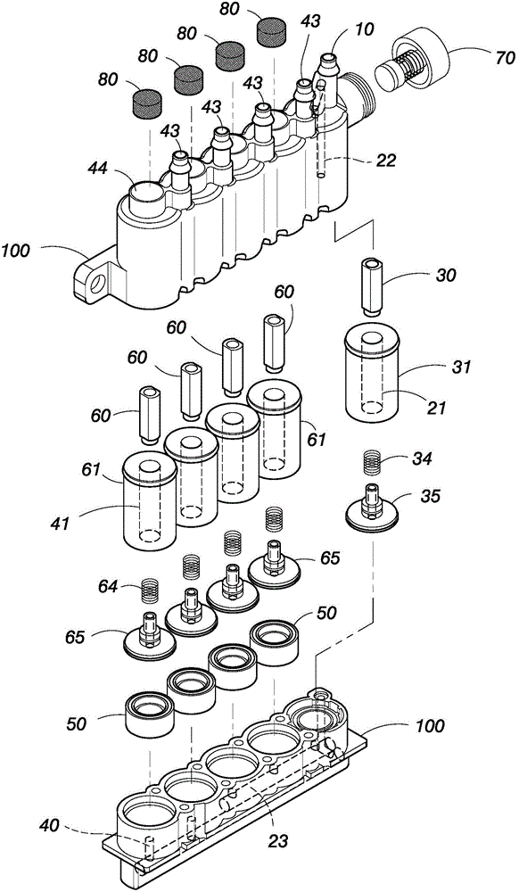
[0038] Please also refer to Figure 4 As shown, the control air valve 200 includes an air intake pipe 10 communicated with the air outlet of the air pump 2, an air intake cha...


PUM


Abstract

The invention provides a combined-type distributing valve group which is particularly suitable for an air bag type inflation and deflation system applied in an automobile chair for improving the comfort performance. The distributing valve group comprises a control air valve and at least two inflation and deflation valves capable of inflating or deflating different air bags. A control air valve is provided with a normally-closed first distribution flow channel which is communicated with one inflation and deflation valve and is provided with a normally-opened second distribution flow channel which is communicated with the other inflation and deflation valve. The two inflation and deflation valves are each provided with a check valve, a normally-opened inflation pipe and a normally-closed deflation opening. Thus, when air enters an air pump, one air bag set can be directly inflated or the other air bag set is inflated through switching of the control air valve and the air pressure in air bags is maintained through the check valves when air is prevented from entering the air pump. When any inflation and deflation valve acts, the air bag corresponding to the inflation and deflation valve is deflated, and therefore the amount of valve bodies and control procedures can be greatly reduced.

Description

technical field [0001] The invention relates to an air distribution valve set installed in an air pump inflation system to inflate at least two sets of air bags, and utilizes the electromagnetic principle to drive various internal functional valve bodies to integrate air intake, inflation, and inversion. Stop and exhaust and other functions. Background technique [0002] Generally, the inflation and exhaust system will set one or several control air valves on the inflation pipeline between the air pump and multiple air bags to switch the air bags to be inflated, and each control air valve and different air bags are connected separately. There are three valve bodies to control the inflation and exhaust of the corresponding air bag. The three valve bodies are: a check valve, an inflation valve capable of controlling the inflation of the air bag, and an exhaust valve bypassing the inflation pipeline; in addition , the inflation and exhaust system has an electronic control modu...

Claims


Application Information

Patent Timeline
IPC IPC(8): F16K11/22F16K31/06
CPCB60N2/914
Inventor 徐正荣
Owner TANGTRING SEATING TECH INC
Why Eureka
Try Eureka