High voltage test circuit and connection method thereof

A high-voltage test and connection method technology, applied in the direction of testing dielectric strength, measuring electricity, measuring electrical variables, etc., can solve the problem that no solution is proposed, the high-voltage withstand test cannot be carried out, and the high-voltage withstand test cannot meet the extreme value requirements, etc. question

Inactive Publication Date: 2016-03-30
STATE GRID BEIJING ELECTRIC POWER +2
View PDF5 Cites 0 Cited by
  • Summary
  • Abstract
  • Description
  • Claims
  • Application Information

AI Technical Summary

Problems solved by technology

[0003] In the existing tests on high-voltage electrical equipment, in order to ensure the normal transmission of electric energy, a high-voltage withstand test is usually carried out on the transmission cable to ensure the normal transmission of electric energy in the future. However, in related technologies, in the high-voltage withstand test, the transmission In the circuit composed of cables, the test voltage and test current in this circuit need to be combined by multiple reactors to compensate the voltage and current in the high voltage withstand test, but the target voltage and target current of the high voltage withstand test still cannot be reached, resulting in high voltage The withstand voltage test cannot meet the extreme value requirements specified in the regulations
[0004] In view of the lack of methods for adjusting the test voltage and test current in the loop to the target voltage and target current of the high-voltage withstand test in the above-mentioned related technologies, the high-voltage withstand test cannot be carried out, and no effective solution has been proposed so far

Method used


Image

  • High voltage test circuit and connection method thereof
  • High voltage test circuit and connection method thereof
  • High voltage test circuit and connection method thereof

Examples


Embodiment 1

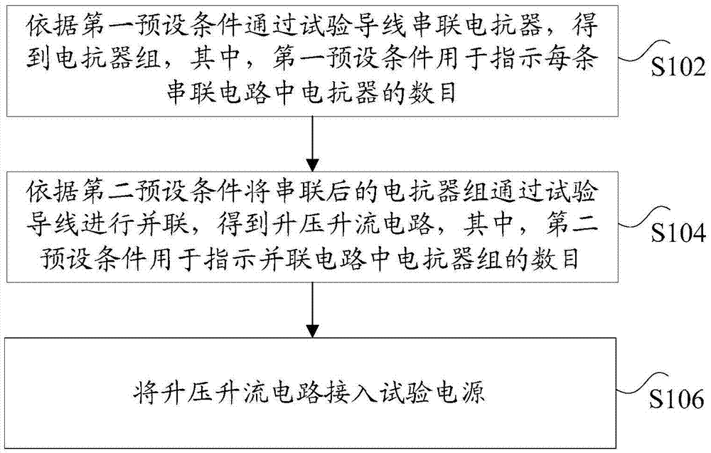
[0022] According to an embodiment of the present invention, a method embodiment of a connection method for a high voltage test circuit is provided, figure 1 It is a schematic flow chart of the connection method of the high voltage test circuit according to the embodiment of the present invention, such as figure 1 As shown, the method includes the following steps:

[0023] Step S102, according to the first preset condition, the reactor group is obtained by testing the wire series reactor, wherein the first preset condition is used to indicate the number of reactors in each series circuit;

[0024] Step S104, according to the second preset condition, the series connected reactor groups are connected in parallel through the test wires to obtain a step-up and current-boosting circuit, wherein the second preset condition is used to indicate the number of reactor groups in the parallel circuit;

[0025] Step S106, connecting the boosting and current boosting circuit to the test pow...

Embodiment 2

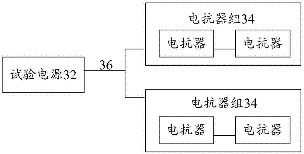
[0043] According to an embodiment of the present invention, an embodiment of a high voltage test circuit is provided, image 3 It is a structural schematic diagram of a high voltage test circuit according to an embodiment of the present invention, such as image 3 As shown, including: test power supply 32, reactor group 34 and test lead 36, wherein,


PUM


Abstract

The invention discloses a high voltage test circuit and a connection method thereof. The connection method comprises: performing serial connection of reactors through a test wire according to a first preset condition, and obtaining a reactor group, wherein the first preset condition is used for indicating the number of the reactors in each series circuit; making the reactor group in serial connection become in parallel connection through a test wire according to a second preset condition, and then obtaining a boost and current rising circuit, wherein the second preset condition is used for indicating the number of the reactors in the parallel circuit; and accessing the boost and current rising circuit to a test power supply. The high voltage test circuit and the connection method can solve the problem that the related art is short of a method for adjusting a test voltage and a test current in a loop to a target voltage and a target current for a high voltage holding test so that the test voltage value for the high voltage holding test cannot achieve an applied voltage value specified by a standard and the current capacity of test equipment is too great.

Description

technical field [0001] The invention relates to the technical field of electrical applications, in particular to a high-voltage test circuit and a connection method. Background technique [0002] In order to ensure the safety of electricity consumption and facilitate the maintenance of daily high-voltage electrical equipment, usually after the specific construction is completed and before the project is put into operation, various power transmission equipment, voltage regulating devices and transmission cables will be pre-tested, and the extreme value test will be carried out in the The working performance of each equipment in each environment, so as to ensure the safety of electricity use in the future, and facilitate the maintenance of daily high-voltage electrical equipment. [0003] In the existing tests on high-voltage electrical equipment, in order to ensure the normal transmission of electric energy, a high-voltage withstand test is usually carried out on the transmis...

Claims


Application Information

Patent Timeline
Patent Type & Authority Applications(China)
IPC IPC(8): G01R31/12
CPCG01R31/1272
Inventor 王唯胡进辉付尚莹陈金爱李海生才忠宾马宝河张竟成
Owner STATE GRID BEIJING ELECTRIC POWER
Why Eureka
Try Eureka