
Power transformer winding fault simulation test method

A power transformer and winding fault technology, applied in the direction of measuring electrical variables, measuring current/voltage, instruments, etc., can solve the problems of researching the influence of winding faults, unacceptable power supply capacity, high requirements for voltage regulators, etc., to achieve strong implementability , Improve the test accuracy, the effect of easy parameters

Active Publication Date: 2012-10-17
JIANGSU ELECTRIC POWER CO +2
View PDF5 Cites 26 Cited by
  • Summary
  • Abstract
  • Description
  • Claims
  • Application Information

AI Technical Summary

Problems solved by technology

[0005] 1. If the power transformer is used to carry the load directly, a large load current is required, not only the power supply capacity of the general laboratory is not allowed, but also a large load device needs to be purchased, which consumes a lot of capital and will waste a lot of electric energy during the test
[0006] 2. Short circuit the low-voltage side of the power transformer, and add a low voltage to the high-voltage side through a voltage regulator, which can be realized in theory, but because of the large load current required, it is required to be adjustable (for example, the S9-M-100 / 10 transformer is 144.3A; S11-M-200 / 10 transformer is 288.7A), if the voltage regulator is directly connected to the power supply, it will output a large current, which will require a high voltage regulator, and the general laboratory The voltage regulator cannot meet such high requirements. In addition, if a relatively high voltage is applied to the transformer, the vibration caused by the iron core will have an impact on the research of winding faults.

Method used


Image

  • Power transformer winding fault simulation test method
  • Power transformer winding fault simulation test method

Examples


Embodiment Construction

[0024] The present invention will be further described below.

[0025] The hardware that the inventive method adopts is as follows:

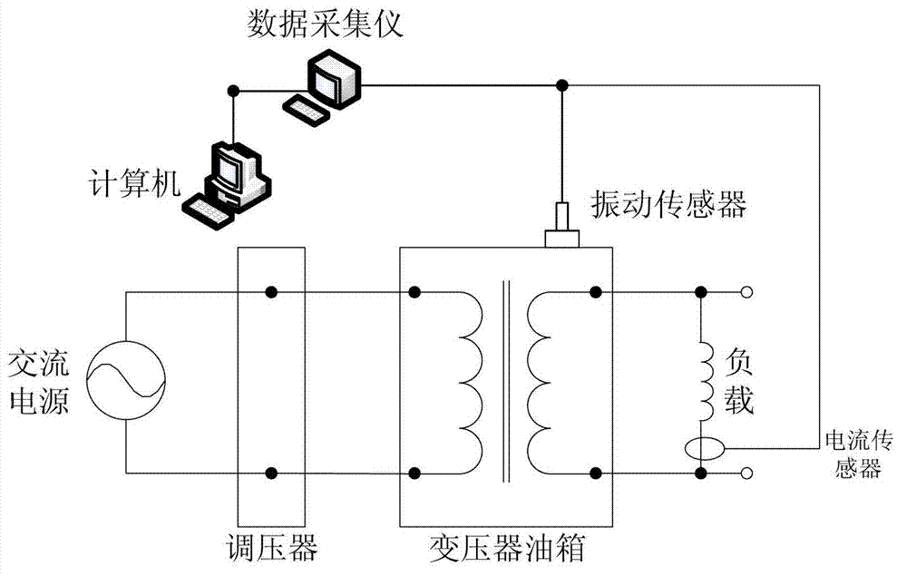
[0026] a. Resistor, function: to limit the influence of the inrush current generated when the power supply is switched on (the general laboratory does not have the power supply capacity that can withstand the no-load closing of the power transformer), short the resistor soon after the power supply is switched on ( within 0.5 seconds after switching on).

[0027] b. Voltage regulator, function: to adjust the voltage on the high-voltage side of the general power transformer, so that the power transformer under test can obtain different load currents required for the test.

[0028] c. General power transformer, function: to further reduce the voltage, so that the size of the load current meets the requirements (the size of the load current should be equivalent to the rated current of the tested transformer), and at the same time make the primary a...


PUM


Abstract

The invention discloses a power transformer winding fault simulation test method and belongs to the field of power transformer winding fault simulation test. The method comprises the following steps that: the high-voltage side of a universal power transformer is connected with an alternating current power supply through a voltage regulator, a resistor for limiting magnetizing rush current is connected in series between the voltage regulator and an electric switch; a bypass switch is connected in parallel at two ends of the resistor; the low-voltage side of the universal power transformer is connected with the low-voltage side of a tested power transformer provided with a winding fault; the high-voltage side of the tested power transformer is in short circuit; the voltage regulator is regulated, so that the tested power transformer acquires different required testing current; and a vibration signal on the surface of an oil tank of the tested transformer is acquired through a vibration sensor, and a current signal which reflects load of the tested transformer is measured through a current sensor so as to be processed and analyzed by a computer. The requirement of the power transformer winding fault simulation test on the power capacity is reduced, the method is easy in operation and readily available in parameters and has universality on similar transformers.

Description

technical field [0001] The invention relates to a power transformer fault diagnosis technology, in particular to a power transformer winding fault simulation test method, which belongs to the field of power transformer winding fault testing. Background technique [0002] The stability and reliability of power transformers greatly affect the safe operation of the entire power grid. Therefore, it is of great significance to carry out research on transformer winding deformation detection and fault diagnosis. [0003] When the power transformer is running stably, the magnetostriction of the silicon steel sheet causes the core to vibrate, and the winding vibrates under the electric field force of the load current. The vibration of the winding and the core is transmitted to the oil tank of the transformer through the transformer body and oil, causing the vibration of the oil tank , The vibration on the surface of the transformer oil tank is closely related to the compaction, displ...

Claims


Application Information

Patent Timeline
IPC IPC(8): G01R31/00G01R19/00G01H1/00
Inventor 马宏忠鞠平陈楷王春宁耿志慧张赢吴益明赵宏飞谢小磊王惠庆
Owner JIANGSU ELECTRIC POWER CO
Learn More