Detection method for grid frequency

A power grid frequency and detection method technology, applied in the field of electrical engineering, can solve problems such as large drift, abnormal frequency and periodic signals, and inability to effectively detect frequency

Inactive Publication Date: 2012-12-26
HUIZHOU SANHUA IND
View PDF4 Cites 25 Cited by
  • Summary
  • Abstract
  • Description
  • Claims
  • Application Information

AI Technical Summary

Problems solved by technology

[0005] From the above analysis, it can be known that when the input mains is a relatively standard sine wave, the detected mains frequency and cycle value are relatively accurate; but when the input power supply voltage has poor stability accuracy or is generated by a diesel generator, it will be A lot of burrs are generated around the zero-crossing point of the sine wave signal, so that the square wave signal input by the microcontroller produces a noisy square wave signal around the zero-crossing point, resulting in abnormal and drifting of the sine wave frequency and period signal detected by the traditional method It is too large to effectively detect its frequency
[0006] Therefore, if we use the traditional method to detect the frequency, the machine will not work normally when the stability accuracy of the input grid mains voltage is poor (especially in countries and regions with poor grids, diesel generators are commonly used for power generation) and the machine will not work normally. In the mode of non-mains power supply, it has a great impact on the performance and life of the machine

Method used


Image

  • Detection method for grid frequency
  • Detection method for grid frequency

Examples


Embodiment 1

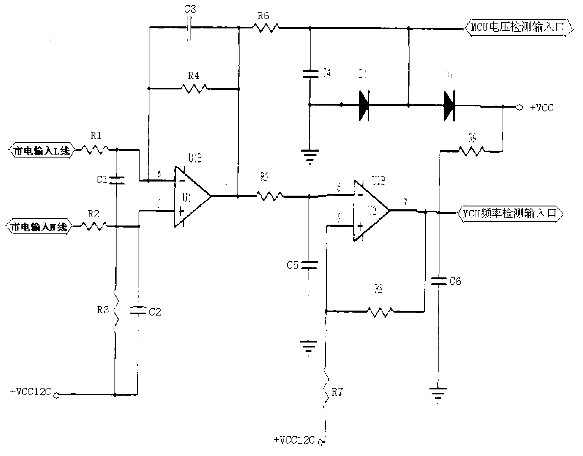
[0037] Such as figure 2 As shown, the L line and N line of the test power supply are connected to the detection circuit, and are connected to the MCU frequency detection input port of the detection circuit through the external interrupt port or input capture port of the microcontroller.

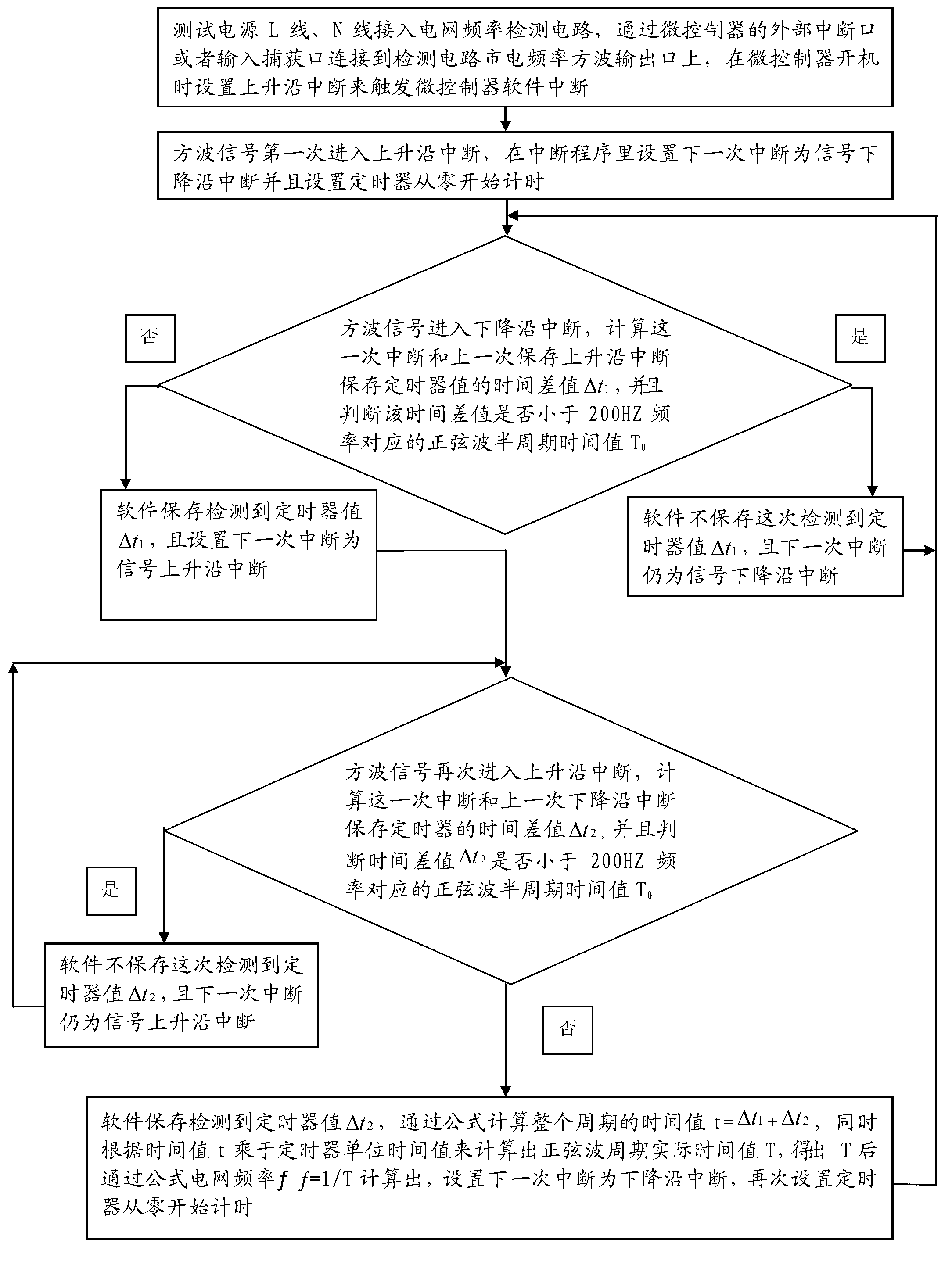
[0038] Such as figure 1 As shown, a grid frequency detection method is characterized in that, comprising the following steps:

[0039] 1) Set the rising edge interrupt to trigger the microcontroller software interrupt when the microcontroller is turned on;

[0040] 2) When the square wave signal enters the rising edge interrupt for the first time, set the next interrupt in the interrupt software of the microcontroller as the signal falling edge interrupt and set the timer to count from zero, and save the timer value as t 0 ;

[0041] 3) The square wave signal enters the falling edge interrupt, at this time the timer value is t n , calculate the interrupt timer value t this time n and th...

Embodiment 2

[0049] Such as figure 2 As shown, the L line and N line of the test power supply are connected to the detection circuit, and are connected to the MCU frequency detection input port of the detection circuit through the external interrupt port or input capture port of the microcontroller.

[0050] Such as figure 1 As shown, a grid frequency detection method is characterized in that, comprising the following steps:

[0051] 1) Set the rising edge interrupt to trigger the microcontroller software interrupt when the microcontroller is turned on;

[0052] 2) When the square wave signal enters the rising edge interrupt for the first time, set the next interrupt in the interrupt program as the signal falling edge interrupt and set the timer to count from zero, and save the timer value as t 0 ;

[0053] 3) The square wave signal enters the falling edge interrupt, at this time the timer value is t n , calculate this time the interrupt timer t n Value and last rising edge interrupt...


PUM


Abstract

The invention discloses a detection method for grid frequency, which mainly comprises the following steps of: (1) connecting a test power supply to a detection circuit, wherein the test power supply can generate a string of square wave signals corresponding to the grid frequency of the test power supply after being subjected to voltage reducing treatment by the detection circuit; (2) obtaining a time difference value Delta t1 of the square wave signals from rising edge interruption to first falling edge interruption by a micro-controller; (3) comparing a sine wave half-cycle time value T0 corresponding to the frequency of 200HZ with the value of Delta t1 to determine whether to store or not; (4) as described in the step (2), obtaining a time difference value Delta t2 of the square wave signals from rising edge interruption to first falling edge interruption by the micro-controller; (5) comparing the sine wave half-cycle time value T0 corresponding to the frequency of 200HZ with the value of Delta t2 to determine whether to store or not; and (6) calculating a cycle actual time value T and grid frequency according to the values of Delta t1 and Delta t2. With the adoption of the detection method, both the standard sine wave input grid frequency and the voltage stabilization precision difference grid frequency can be detected.

Description

technical field [0001] The invention relates to the technical field of electric engineering, in particular to a method for detecting the operating frequency of a grid voltage. Background technique [0002] In the power system, the frequency of the power grid is one of the three major indicators of power quality. The frequency of the power grid reflects the balance between the active power of the power generation and the load, and is an important control parameter for the operation of the power system. The guide vane is damaged, and the service life of the governor is reduced. For users, although many user equipment can work normally in a wide frequency range, with the development of science and technology, some new electronic equipment and precision processing equipment put forward higher requirements for the power grid, frequency fluctuations, It will degrade the quality of the user's product or damage the equipment. Therefore, the grid frequency is the main monitoring pa...

Claims


Application Information

Patent Timeline
Patent Type & Authority Applications(China)
IPC IPC(8): G01R23/02
Inventor 兰维机张世桐咸立坤
Owner HUIZHOU SANHUA IND
Why Eureka
Try Eureka