
System for testing power quality monitoring device and testing method thereof

A power quality monitoring and power quality technology, applied in the direction of measuring devices, measuring electrical variables, instruments, etc., can solve the problems of extended test time, tediousness, and increased complexity of system applications, and achieve the effect of improving intelligence

Active Publication Date: 2015-04-29
ELECTRIC POWER RES INST OF GUANGXI POWER GRID CO LTD
View PDF6 Cites 26 Cited by
  • Summary
  • Abstract
  • Description
  • Claims
  • Application Information

AI Technical Summary

Problems solved by technology

The commonly used standard sources for power quality monitoring device testing are precision and expensive equipment. During the test process, the output of the standard source is overloaded due to improper control. On the one hand, it will affect the service life and precision of the standard source. The test process is terminated and the test needs to be restarted
[0005] (2) Does not have the function of testing the correctness of the wiring of the power quality monitoring device
When testing power quality monitoring devices in batches, especially multi-circuit monitoring devices, there are many voltage and current signal lines in the device, and the wiring work is very cumbersome, and it is inevitable that there will be wiring errors.
Once the wiring is wrong, it will cause the accuracy test results of some power quality indicators to be unqualified, so it is necessary to find the cause and retest, resulting in extended test time
[0006] (3) Does not have the test function of the integrity of the closed-loop test environment
Fully automatic testing of power quality monitoring devices requires the construction of a closed-loop testing environment, and any failure in a small link will cause the automatic testing system to fail to operate normally and correctly
Due to the large number of components of the fully automatic test system, it will be very cumbersome to manually find out the reason after the system fails to operate normally.
[0007] None of the above problems is a deficiency in the accuracy test function of the power quality monitoring device test system, but it will also lead to an increase in the complexity of the system application and a significant drop in test efficiency. Therefore, it is necessary to modify the test system to further improve the intelligence of the system.

Method used


Image

  • System for testing power quality monitoring device and testing method thereof
  • System for testing power quality monitoring device and testing method thereof

Examples


Embodiment Construction

[0024] The technical solutions in the embodiments of the present invention will be clearly and completely described below in conjunction with the accompanying drawings in the examples of the present invention. Obviously, the described embodiments are only some of the embodiments of the present invention, not all of them. Based on the embodiments of the invention, all other embodiments obtained by persons of ordinary skill in the art without creative efforts fall within the protection scope of the present invention.

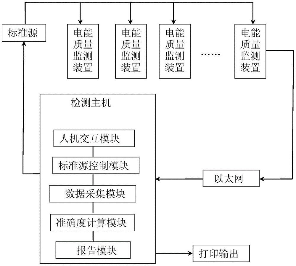
[0025] combine figure 1 , a system for testing a power quality monitoring device, the system includes a detection host, a standard source, and a power quality monitoring device, the detection host communicates with the standard source through a GBIP bus, and the standard source and the power quality monitoring device pass the test The signal lines are electrically connected, and the power quality monitoring device forms a closed-loop communication control system w...


PUM


Abstract

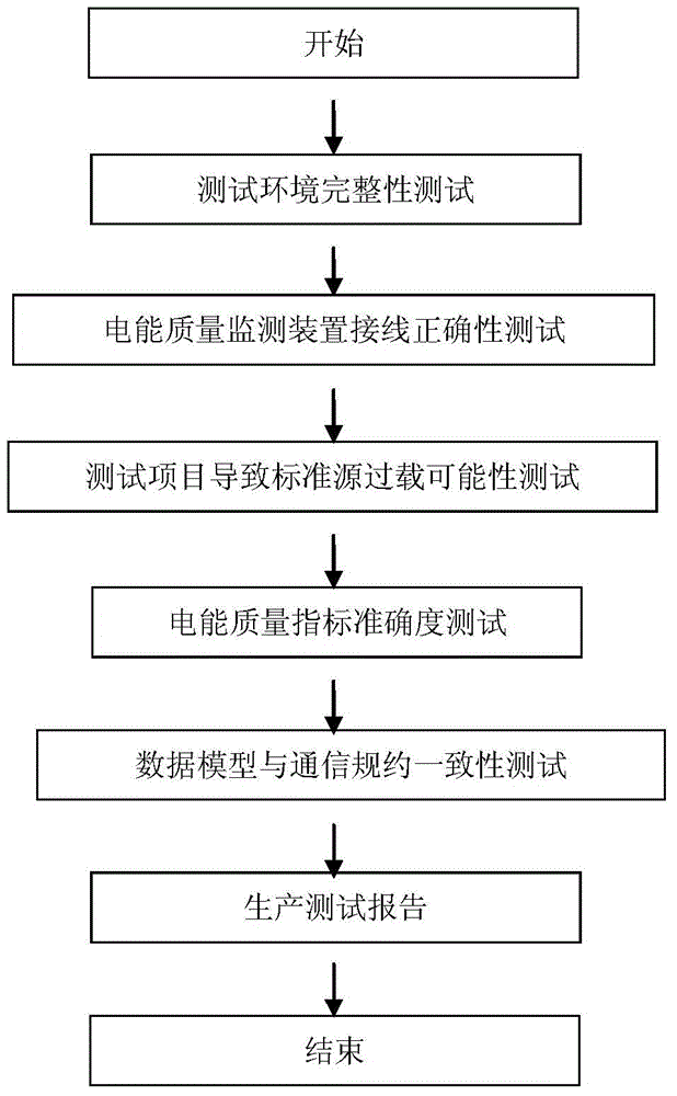
The invention belongs to the technical field of full automatic detection of power equipment and particularly relates to a system for testing a power quality monitoring device and a testing method of the system. The system comprises a detecting host, a standard source and the power quality monitoring device. The detecting host is connected with the stand source through a GBIP bus in a communicating mode. The standard source is electrically connected with the power quality monitoring device through a test signal line. The power quality monitoring device and the detecting host form a closed loop communication control system through the Ethernet. According to the system and the testing method of the system, the accuracy of power quality indexes, a data model and communication protocols can be tested, the automatic system detection and fault recognition alarm functions of standard source overload judgment, power quality monitoring device wiring correctness, closed loop testing environment integrity and the like can be achieved, the intelligence and the automation degree of testing the power quality monitoring device are improved, and the work benefits of testing the power quality monitoring device are increased.

Description

technical field [0001] The invention belongs to the technical field of fully automatic detection of electric power equipment, and in particular relates to a system for testing a power quality monitoring device and a testing method thereof. Background technique [0002] The local communication unit of the acquisition terminal is to realize the data communication between the acquisition terminal and the user's electric energy metering device. The communication modes of the communication unit mainly include public network communication, private network communication, carrier communication and small wireless communication. Network communication module, carrier communication module and small wireless communication module, each communication module has a local port and a channel port; the external dimensions, power supply, status, control, communication interface, communication protocol and communication timing of these ports are guaranteed communication modules A necessary condit...

Claims


Application Information

Patent Timeline
Patent Type & Authority Applications(China)
IPC IPC(8): G01R35/00
Inventor 陈卫东郭敏金庆忍楚红波刘路
Owner ELECTRIC POWER RES INST OF GUANGXI POWER GRID CO LTD
Learn More