
Device & method for smart, non-habituating, automatic bird deterrent system

a technology of automatic deterrent system and device, applied in the field of deterrent system, can solve the problems of bird health, billions of dollars in damage to aircraft, and significant loss of life, and achieve the effects of other hazards, and reducing the risk of birds

Active Publication Date: 2013-04-25
ACCIPITER RADAR TECH
View PDF7 Cites 62 Cited by
  • Summary
  • Abstract
  • Description
  • Claims
  • Application Information

AI Technical Summary

Benefits of technology

The present invention provides improved bird-deterrent systems that are more intelligent, automated, flexible, and reliable. This results in better protection of protected areas from birds.

Problems solved by technology

Consider for example, mining and oil operations with associated tailings ponds that may be harmful to birds.
Electrical power generation structures such as wind turbines pose hazards to birds because birds flying through wind farms, especially during low visibility, can come in contact with turbine blades, which rotate within a confined altitude band up to a couple of hundred meters above the ground.
Birds are a significant hazard to aviation safety.
Billions of dollars in damage to aircraft and significant loss of life have been recorded as the result of birds colliding with aircraft (referred to as bird-aircraft strikes, or simply bird strikes), particularly while aircraft are on approach or departure in the vicinity of airports.
Birds do not survive bird strikes.
Automated deterrents such as propane cannons, effigies, acoustic devices that broadcast aversive auditory emissions such as alarm, distress, and predator vocalizations, and lasers operated in low-light have been used with some success but suffer from habituation—i.e., the birds get used to them and the deterrents eventually lose their effectiveness in harassing and deterring birds.
These human-operated deterrents, however, are impractical to use in a continuous fashion over large protected areas or at night.
While radar-activated deterrent systems have been reported in use in rare cases, their effectiveness has not been quantified and reported.
In these limited cases, 2D radars were employed that did not provide bird altitude selectivity over the protected area.

Method used


Image

  • Device & method for smart, non-habituating, automatic bird deterrent system
  • Device & method for smart, non-habituating, automatic bird deterrent system
  • Device & method for smart, non-habituating, automatic bird deterrent system

Examples


Embodiment Construction

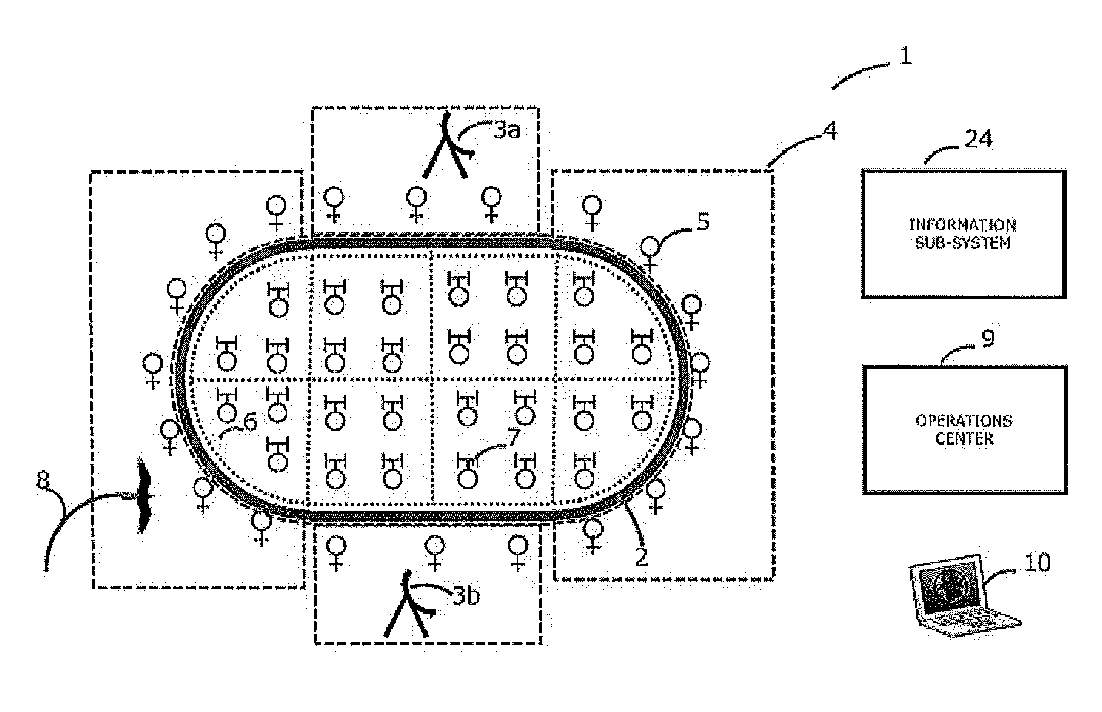
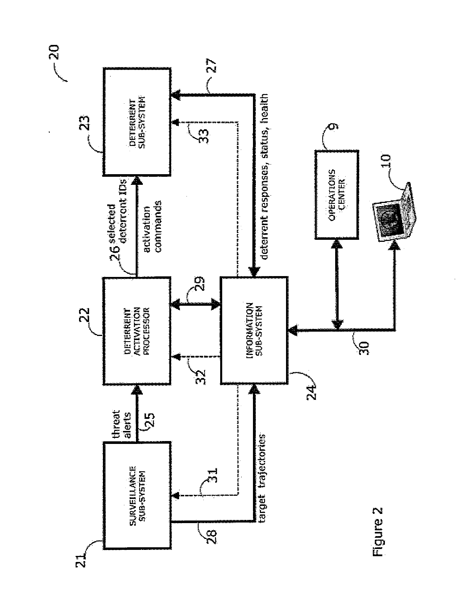
[0075]A deployment diagram 1 of a typical, automated bird deterrent system 20 (see FIG. 2) in accordance with the present invention is shown in FIG. 1. A protected area 2 represents a region that threatens birds or is threatened by birds. For the example of FIG. 1, the protected area 2 is a large tailings pond. A surveillance subsystem 21 (see FIG. 2) monitors birds that may come into the protected area and consists of two sensor apparatuses 3a and 3b located in this example on either side of the protected area 2. The sensor apparatuses 3a and 3b are preferably avian radars as described previously herein which together provide coverage of birds in the vicinity of the protected area. Two virtual lines of defense are implemented in this example, an outer line of defense and an inner line of defense. The surveillance subsystem 21 defines in this case four outer intrusion zones 4 that surround the tailings pond that make up the outer line of defense. A number of deterrent apparatuses 5 ...


PUM


Abstract

Operation of a bird deterrent system includes i. measurement of bird habituation to activation of deterrent devices; ii. reduction of habituation through increased selectivity in activating deterrents only for birds posing a threat to or threatened by a protected area, and in particular, those within threat altitudes; iii. provision of analytical data in support of safety management systems, risk management, etc.; iv. integrated, wide-area radar coverage with multiple virtual intrusion zones providing multiple lines of defense around and over very large protected areas.

Description

FIELD OF THE INVENTION[0001]This invention relates to deterrent systems and methods to keep birds away from protected areas that are either threatened by birds or pose a threat to birds. The invention is particularly useful for protecting birds from harmful effects of ponds generated during oil and mining processes, for protecting birds from power generation and transmission structures such as wind farms, for prevention of bird-aircraft strikes at airports to enhance aviation safety, and for protecting crops from birds to enhance yield.BACKGROUND OF THE INVENTION[0002]Several applications require keeping birds away from protected areas, which we define herein as geographical areas that either threaten birds and / or are threatened by birds. Consider for example, mining and oil operations with associated tailings ponds that may be harmful to birds. Operators and regulators desire economical devices and methods designed to help keep birds from landing on these protected areas, i.e. the ...

Claims


Application Information

Patent Timeline
IPC IPC(8): A01K29/00
CPCA01M29/06A01M29/10A01M29/18A01M31/002A01M29/00A01M29/16
Inventor NOHARA, TIMOTHY J.UKRAINEC, ANDREW M.JONES, GRAEME S.BEASON, ROBERT C.WEBER, PETER T.COSTA, DOMINGOS NELSONKRASNOR, CARL
Owner ACCIPITER RADAR TECH
Learn More