
A Method of Improving Radar Angle Measuring Range

A range and angle measurement technology, which is applied in the field of improving the radar angle measurement range, can solve the problems of small angle measurement range and sudden change of angle measurement, and achieve the effect of expanding the angle measurement range and accurate compensation

Active Publication Date: 2018-01-19
DALIAN ROILAND SCI & TECH CO LTD
View PDF5 Cites 0 Cited by
  • Summary
  • Abstract
  • Description
  • Claims
  • Application Information

AI Technical Summary

Problems solved by technology

The angle measurement range of the phase comparison method is mainly related to the antenna spacing and the frequency of the radar signal. The existing angle measurement range is small. After exceeding a certain range, the measured angle changes suddenly, and certain compensation is required.

Method used


Image

  • A Method of Improving Radar Angle Measuring Range
  • A Method of Improving Radar Angle Measuring Range

Examples


Embodiment 1

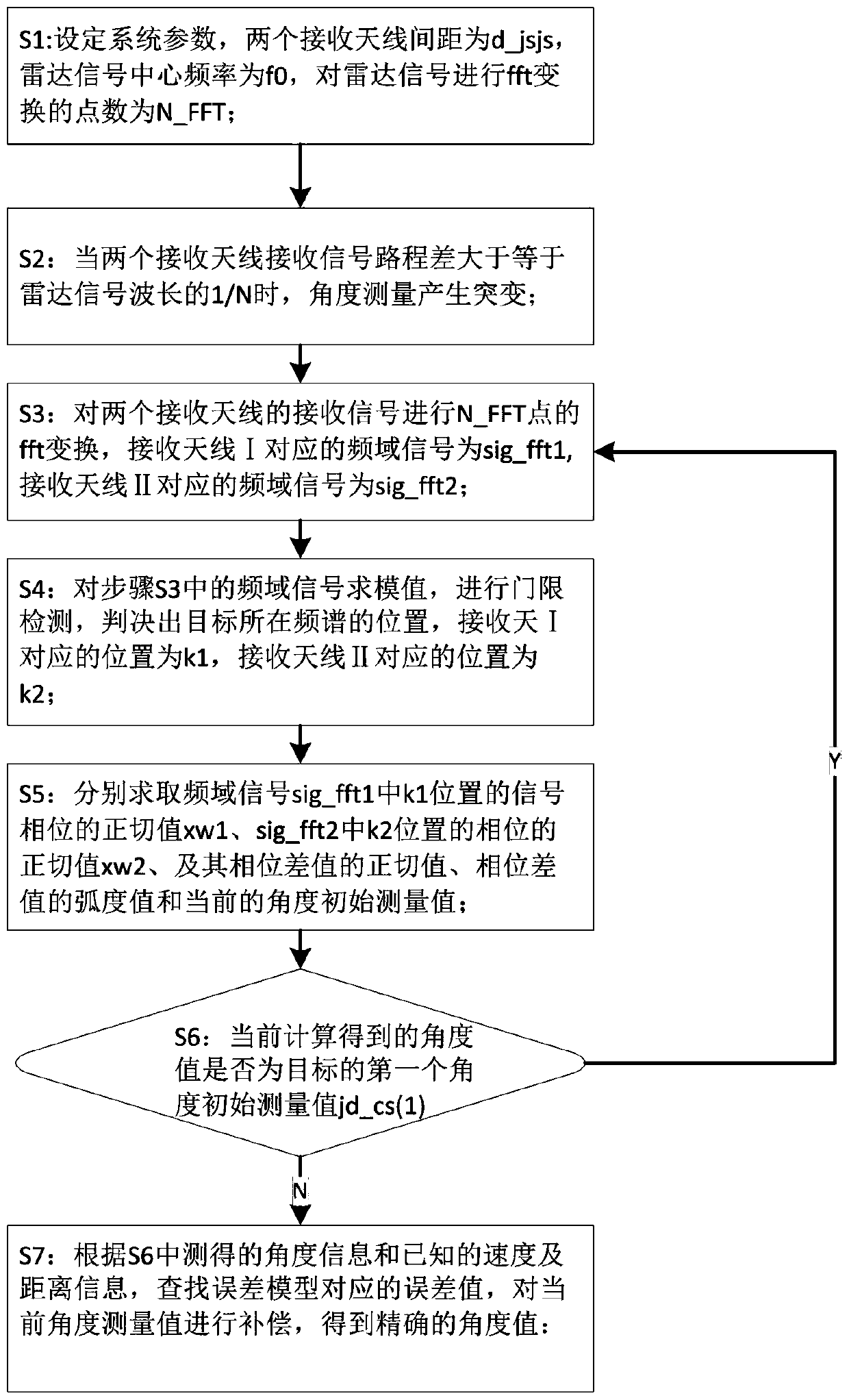
[0035] A method to increase the range of radar angle measurement. The radar waveform is a constant frequency wave or a linear frequency modulation continuous wave. This method is realized by one transmitting antenna and two receiving antennas. The receiving antenna I is located between the receiving antenna II and the transmitting antenna. Take the receiving antenna II as the origin of the coordinates, the normal direction of the receiving antenna II is the y-axis, and the receiving antenna I and the transmitting antenna are located on the positive semi-axis of the x-axis, and establish the coordinate axis. For example, the target angle is 20°, which refers to the receiving antenna 2 The angle between the direction vector to the target and the normal direction of the receiving antenna 2 is 20°, and the target is located on the right side of the coordinate axis. The target angle is -30°, which means that the angle between the direction vector from the receiving antenna 2 to the t...


PUM


Abstract

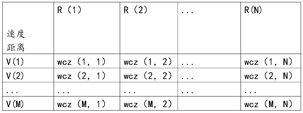
The invention discloses a method for improving a radar angle measurement scope, comprising steps of hypothesizing that only one target exist, finding the position of the target in a frequency spectrum through threshold detection, obtaining phase difference of signals received by two reception antennas through a phase comparison method, and performing correction on the detected according to detected target speed and target approaching far away information. The invention enables the measurable angle scope to be doubled, performs error compensation on the final result according to an established error model, and improves the angle measurement accuracy.

Description

Technical field [0001] The invention belongs to the field of radar angle measurement, and specifically is a method for improving the range of radar angle measurement. Background technique [0002] Angle measurement is to determine the pitch and azimuth angle of the target, and it is an important part of target orientation and precise guidance. There are many existing radar angle measurement algorithms, such as amplitude comparison method, phase comparison method, array scanning angle measurement, single pulse angle measurement, super-resolution angle measurement, etc. The angle measurement range of the phase comparison method is mainly related to the antenna spacing and the frequency of the radar signal. The existing angle measurement range is relatively small. After a certain range, the measured angle changes suddenly and requires certain compensation. Summary of the invention [0003] In order to solve the above-mentioned problems in the prior art, the present invention provide...

Claims


Application Information

Patent Timeline
Patent Type & Authority Patents(China)
IPC IPC(8): G01S7/41
CPCG01S7/41
Inventor 田雨农苏鹏达周秀田史文虎
Owner DALIAN ROILAND SCI & TECH CO LTD
Learn More