Automatic velocity spectrum interpretation method based on model and global optimization

A technology of global optimization and automatic interpretation, applied in seismic signal processing and other directions, it can solve problems such as complex algorithms, and achieve the effect of shortening processing cycles and reducing manual workload.

Active Publication Date: 2016-03-30
CHINA PETROLEUM & CHEM CORP +1
View PDF5 Cites 8 Cited by
  • Summary
  • Abstract
  • Description
  • Claims
  • Application Information

AI Technical Summary

Problems solved by technology

Although this type of method has high comput

Method used


Image

  • Automatic velocity spectrum interpretation method based on model and global optimization
  • Automatic velocity spectrum interpretation method based on model and global optimization
  • Automatic velocity spectrum interpretation method based on model and global optimization

Examples


Example Embodiment

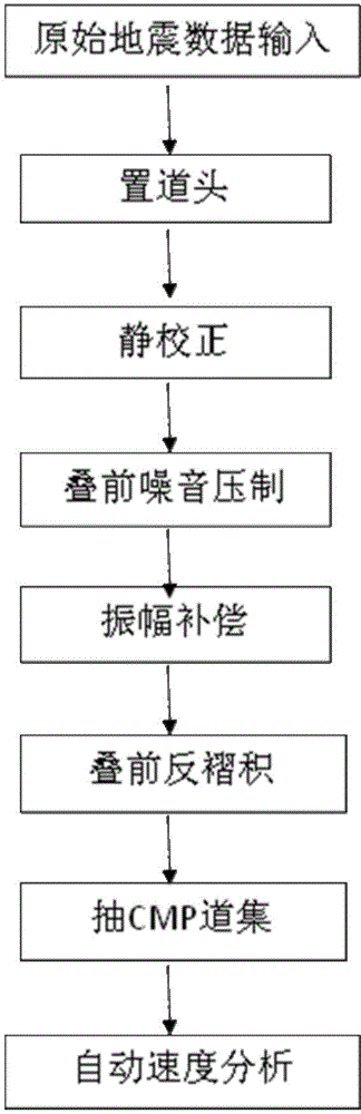
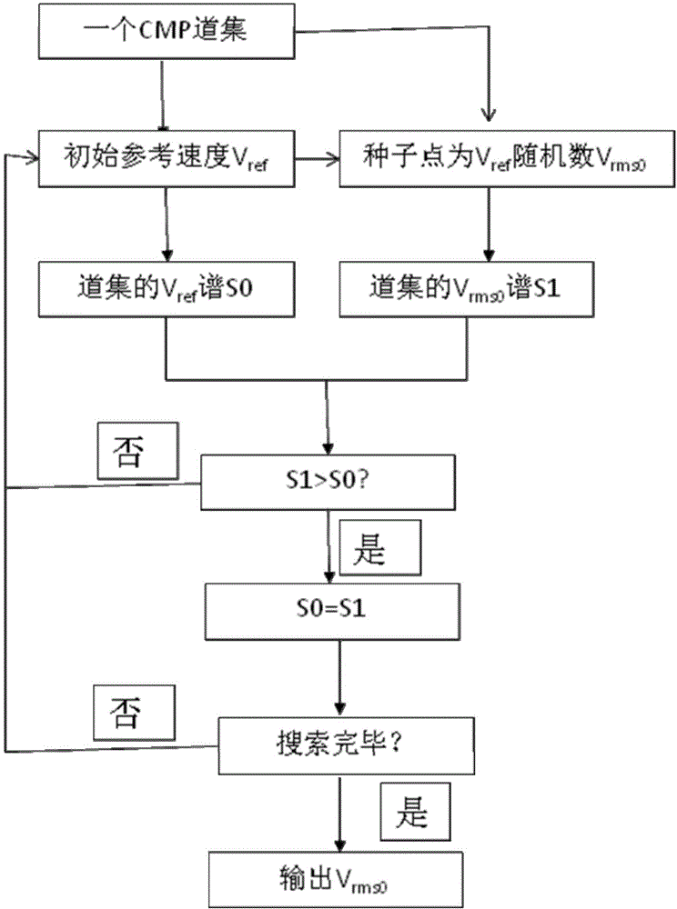
[0020] Below in conjunction with accompanying drawing, the present invention is described in further detail:
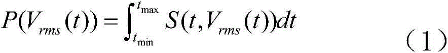
[0021] In general, automatic velocity analysis solves extreme value problems in the form of:

[0022] P ( V rms ( t ) ) = ∫ t min t max S ( t , V rms ( t ) ) dt - - - ( 1 )

[0023] where S is the velocity spectrum, t is the time sample, and Vrms is the superposition velocity.

[0024] steps such as figure 1 As shown, usually the last step is manual...


PUM


Abstract

The invention provides an automatic velocity spectrum interpretation method based on a model and global optimization, and belongs to the field of oil gas and coal-bed gas seismic exploration and development. The method comprises the following steps: (1) preprocessing original seismic data, namely, a common-shot gather; (2) taking the CMP gather obtained in step (1) as input data, arbitrarily giving a reference velocity as an initial reference velocity, and using the initial reference velocity to carry out NMO correction on the CMP gather; (3) for a time moment t, generating a random number by taking the reference velocity as a seed point, taking the random number as a stacking velocity VrmsO, solving VrmsO to obtain the optimal VrmsO, and solving VrmsO at next time moment until VrmsO of all moments t on the CMP gather is solved; and (4) inputting next CMP gather, and repeating the steps (2) and (3) until VrmsO of all input CMP points is solved.

Description

technical field [0001] The invention belongs to the field of seismic exploration and development of oil and gas and coalbed methane, and in particular relates to an automatic interpretation method of velocity spectrum based on model and global optimization. Background technique [0002] In the processing of seismic data of oil and gas exploration, the stacking velocity analysis is not only the basic but also very important content of seismic data processing. It is the basis for realizing the stacking of multiple CMP gathers in seismic exploration, and it is also the basis for supporting high-precision seismic imaging velocity modeling. Base. [0003] Stacking velocity analysis is based on the realization form of velocity spectrum. According to the principle of normal time difference between the excitation and reception of seismic signals, a series of predetermined velocity curves are used to scan, and the normal time difference of each channel in the CMP gather is calculated...

Claims


Application Information

Patent Timeline
IPC IPC(8): G01V1/28
Inventor 刘百红孙成龙许自龙
Owner CHINA PETROLEUM & CHEM CORP
Why Eureka
Try Eureka