Time-space array differential electromagnetic prospecting method

A differential and array technology, applied in the field of electromagnetic detection, can solve the problems of long duration, unsatisfactory processing effect and need to be improved, and achieve the effect of flexible acquisition method

Active Publication Date: 2016-03-30
CENT SOUTH UNIV
View PDF4 Cites 10 Cited by
  • Summary
  • Abstract
  • Description
  • Claims
  • Application Information

AI Technical Summary

Benefits of technology

This technology allows for flexibility with regards to acquiring measurements from an unknown area without having specific equipment installed at that location. It uses multiple sensors placed around it's circumference or inside its walls instead of just being limited to certain areas only. By analyzing these signals together they can identify different types of problems such as environmental issues like groundwater contamination, faulty pipes, etc., which may be difficult if done manually.

Problems solved by technology

This patented technical solution described involves improving the performance of traditional techniques that use only weakly related sources like magnetometers or audio frequency devices. However, these solutions may also contain significant amounts of irrelevant background noise which can make it challenges to accurately detect relevant features within an area due to their high degree of coherence.

Method used


Image

  • Time-space array differential electromagnetic prospecting method
  • Time-space array differential electromagnetic prospecting method
  • Time-space array differential electromagnetic prospecting method

Examples


Embodiment Construction

[0178] The present invention will be further described below in conjunction with the accompanying drawings and specific embodiments.

[0179] The space-time array differential electromagnetic prospecting method provided by the present invention includes the following steps:

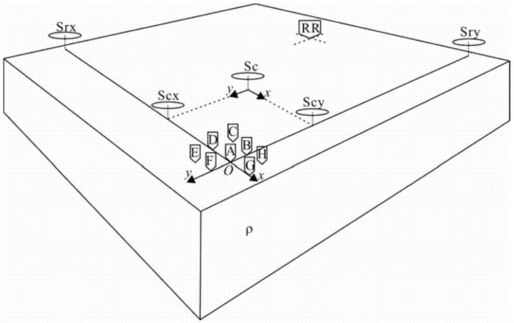
[0180] (1) Observation design: Determine the observation target and depth range, determine the observation frequency range according to the actual exploration depth requirements and the background conductivity of the survey area, and determine the synchronous observation time length and signal sampling rate of the measurement points according to the required observation frequency; Design survey lines and survey points for detection targets and survey areas; figure 1 As shown, array observation points A, B, ... are deployed in the survey area, and the far reference point RR is arranged in a low-noise area far enough away from the survey area;

[0181] (2) Device layout: use multiple electromagnetic field...


PUM


Abstract

The invention provides a time-space array differential electromagnetic prospecting method comprising the following steps: (1) carrying out multi-time-window synchronous array data acquisition at multiple measuring points in a space and a distant reference point; (2) constructing a measuring point signal spatial-temporal data matrix X, a natural electromagnetic field signal spatial-temporal data matrix Xr and a related noise field signal spatial-temporal data matrix Y according to observation data; (3) decomposing Xr to solve a natural electromagnetic field source polarization parameter Alpha, decomposing Y to solve a related noise field source polarization parameter Beta, and solving the space modulus U of each measuring point relative to a natural field source and the space modulus V of each measuring point relative to a related noise field source based on Alpha, Beta and X; and (4) working out the natural field tensor impedance and the related noise field tensor impedance of each measuring point based on U and V. According to the invention, the mode of data acquisition is flexible, noise is allowed to exist in all measuring channels and time windows, signal-noise separation is realized according to the features of field source signals, and the natural field tensor impedance and the related noise field tensor impedance of all the measuring points can be obtained through one processing.

Description


Claims


Application Information

Patent Timeline
Owner CENT SOUTH UNIV
Why Eureka
Try Eureka