Revolution cabinet real-time inventory verification and positioning system

A positioning system and rotary cabinet technology, applied in the field of rotary cabinet disk storage and positioning system, can solve the problems of long time, waste of time and resources, inconvenient operation, etc., and achieve the effect of small power loss

Inactive Publication Date: 2016-03-30
李江波
View PDF5 Cites 6 Cited by
  • Summary
  • Abstract
  • Description
  • Claims
  • Application Information

AI Technical Summary

Problems solved by technology

In the design, in order not to affect the pick-up operation of the pick-up window, the general radio frequency antenna or two-dimensional code scanner is set above or below the cabinet, and only when the label on the item passes through the front of the radio frequency antenna or two-dimensional code scanner The label on the item can be accurately identified and read only when it is in the correct position, but the real-time monitoring of the item cannot be realized when the item is deposited or picked up. After each item is deposited or retrieved, the rotary layer-selecting filing cabinet needs to be removed. The box runs to the position where the radio frequency RFID antenna or the two-dimensional code scanner is directly facing, so as to scan, identify and read the item label after depositing and taking it out through the radio frequency antenna or two-dimensional code scanner. The operation is very inconvenient and wastes time. and resources
[0004] At present, the common RFID antenna is installed on the front panel of the front of the bucket board, which can be used for storage and positioning, but the positioning layer is not located in the access window, that is, the positioning of the wrong layer, which relies on software to correct, so it is impossible to track items in real time.
[0005] Using the code scanning technology, it is installed on the back of the bucket plate, which can be used for inventory and positioning, but it cannot be real-time and takes a long time, that is, it needs to be carried out after each floor is stopped.

Method used


Image

  • Revolution cabinet real-time inventory verification and positioning system
  • Revolution cabinet real-time inventory verification and positioning system
  • Revolution cabinet real-time inventory verification and positioning system

Examples


Embodiment Construction

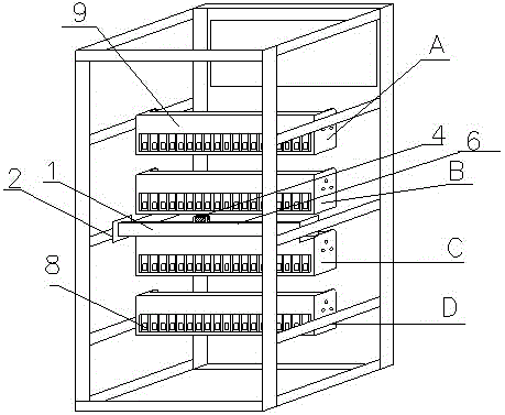
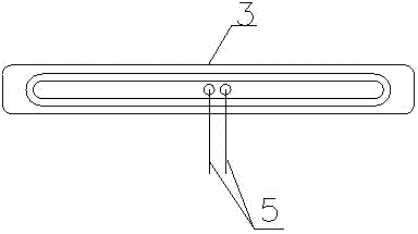
[0022] like Figure 1-4 As shown, the present invention discloses a real-time inventory and positioning system for a revolving cabinet. The front panel of the revolving cabinet is provided with an access window, and an RFID antenna packaging box 6 is installed between the horizontal columns on both sides of the revolving cabinet. The RFID antenna package An RFID antenna 3 is arranged in the box 6, and a feeder 5 is connected to the RFID antenna 3, and the feeder 5 is connected to the reader 4 arranged on the RFID antenna packaging box 6;

[0023] There is a transmission device in the revolving cabinet, and the transmission device drives the bucket plate 9 in the revolving cabinet to move around the RFID antenna 3 along the arc track;

[0024] An electronic tag 8 is provided on the items in the bucket board 9;

[0025] The RFID antenna 3 is corresponding to the access window;

[0026] When the electronic tags 8 of the items in the bucket board 9 correspond to the RFID antenna...


PUM


Abstract

The invention belongs to the field of revolution cabinet inventory verification and positioning systems. A revolution cabinet real-time inventory verification and positioning system is characterized in that an access window is formed on a front panel of a revolution window, an RFID antenna packaging box is clamped between transverse columns on two sides of the revolution cabinet, the RFID antenna packaging box is internally provided with an RFID antenna, the RFID antenna is connected with feedback lines, and the feedback lines are connected with a reader on the RFID antenna packaging box; the revolution cabinet is internally provided with a transmission device, and the transmission device drives bucket plates in the revolution cabinet to move around the RFID antenna along an arc track; articles in the bucket plates are provided with electronic labels; the RFID antenna is corresponding to the access window; and when the articles with the electronic labels right face the RFID antenna through windows on back sides of the bucket plates, the reader finishes inventory verification and positioning. The revolution cabinet inventory verification and positioning system is simple in structure, the radio frequency antenna is parallel to the bucket plates, and barrier-free communication between the antenna and the article labels is realized.

Description

technical field [0001] The invention relates to the field of rotary cabinet disk storage and positioning system, in particular to a rotary cabinet real-time disk storage and positioning system. Background technique [0002] Existing filing cabinets rarely have the function of scanning code identification, and generally the filing cabinets with this function use a code scanning gun to enter the barcode of the file before the file is put into the warehouse, and cannot perform tracking operations after the file is put into the cabinet. [0003] More advanced filing cabinets use radio frequency technology or direct QR code scanning technology, which is rarely used in rotary layer selection filing cabinets. In the design, in order not to affect the pick-up operation of the pick-up window, the general radio frequency antenna or two-dimensional code scanner is set above or below the cabinet, and only when the label on the item passes through the front of the radio frequency antenna...

Claims


Application Information

Patent Timeline
Patent Type & Authority Applications(China)
IPC IPC(8): G06K7/10G06K19/06B65G1/12
Inventor 李治中郑笛王俊沈超玲李江波
Owner 李江波
Why Eureka
Try Eureka