Generator power transduction device and method

A technology of generator power and generator, applied in the field of power system, can solve the problems of inability to realize two outputs of power, malfunction of DEH valve quick control, large fault current, etc.

Active Publication Date: 2016-03-30
NR ELECTRIC CO LTD +1
View PDF2 Cites 9 Cited by
  • Summary
  • Abstract
  • Description
  • Claims
  • Application Information

AI Technical Summary

Problems solved by technology

When a fault occurs outside the unit area or an adjacent transformer runs out, due to factors such as a large fault current or non-periodic components, the current waveform of the measuring-level current transformer at the generator end is distorted, resulting in the power transmitter being unable to be true. Reflect the current power of the generator and output wrong power, even make DEH or DCS malfunction
According to on-site feedback, there have been many accidents in domestic thermal power units due to the output distortion of the power transmitter that caused the rapid control of the DEH valve to malfunction. In some cases, multiple units were shut down, and the consequences were quite serious.
[0003] Chinese patent application number 201410131932.X proposes a generator power transmission method based on the overcurrent fault identification criterion. This method uses the full-wave Fourier algorithm, and the implementation method is simple, but there are still some unresolved problems: (1 ) When a fault occurs in the light load condition of the generator, the sensitivity of the overcurrent fault identification criterion is not high
When a fault occurs under the light-load condition of the generator and the fault component contains a non-periodic component, because the fault current is not large, the

Method used


Image

  • Generator power transduction device and method
  • Generator power transduction device and method
  • Generator power transduction device and method

Examples


Embodiment Construction

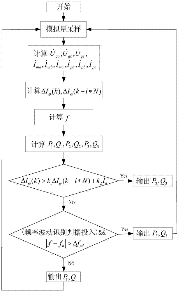
[0039] The technical solutions of the present invention will be described in detail below in conjunction with the accompanying drawings.

[0040] The invention provides a generator power transmission device, which includes a detection unit, a calculation unit and a judgment unit, wherein the detection unit is used to detect the three-phase voltage of the voltage transformer at the machine end of the generator and the three-phase current of the current transformer at the machine end measurement level And the three-phase current of the machine-side protective current transformer.

[0041] The calculation unit is used to calculate the fundamental wave phasor of the three-phase voltage of the generator terminal voltage transformer, the fundamental wave phasor of the three-phase current of the machine terminal measurement level current transformer and the voltage and current obtained by the detection unit. The fundamental wave phasor of the three-phase current of the protective cur...


PUM


Abstract

The invention discloses a generator power transduction method. The generator power transduction method comprises the steps: firstly collecting generator terminal voltage transformer three-phase voltage, generator terminal measurement-level current transformer three-phase current and generator terminal protection-level current transformer three-phase current in real time, secondly respectively calculating fundamental wave phasors of the generator terminal voltage transformer three-phase voltage, the generator terminal measurement-level current transformer three-phase current and the generator terminal protection-level current transformer three-phase current, and calculating generator terminal protection-level current transformer three-phase current fault component, generator frequency, power 1, power 2 and power 3; utilizing current fault component criterion with a floating braking threshold feature; if the criterion is met, outputting the power 2; if the criterion is not met, identifying the criterion by utilizing frequency fluctuation; if the criterion function is inputted and the criterion is met, outputting the power 3; if the criterion function is not inputted and the criterion is not met, outputting the power 1. According to the generator power transduction method, the criterion false operation when a system generates frequency deviation or oscillation can be avoided, and active power is correctly outputted. The invention further discloses a generator power transduction device.

Description

technical field [0001] The invention belongs to the field of power systems, and in particular relates to a generator power transmission device and a transmission method. Background technique [0002] The traditional generator power transmitter collects the generator terminal voltage and the current transformer current of the machine terminal measurement level, and uses the time division multiplier principle to generate an analog power signal, which is supplied to the distributed control system (DCS) of the unit and the digital electro-hydraulic control of the steam turbine. system (DEH) used. When a fault occurs outside the unit area or an adjacent transformer runs out, due to factors such as a large fault current or non-periodic components, the current waveform of the measuring-level current transformer at the generator end is distorted, resulting in the power transmitter being unable to be true. Reflect the current power of the generator and output wrong power, even make ...

Claims


Application Information

Patent Timeline
IPC IPC(8): H02J3/48
CPCH02J3/48
Inventor 李华忠姬生飞陈俊王光张琦雪钟守平郭自刚陈佳胜王凯
Owner NR ELECTRIC CO LTD
Why Eureka
Try Eureka